Let Sino's Lamination Stacks Empower Your Project!
To speed up your project, you can label Lamination Stacks with details such as tolerance, material, surface finish, whether or not oxidized insulation is required, quantity, and more.
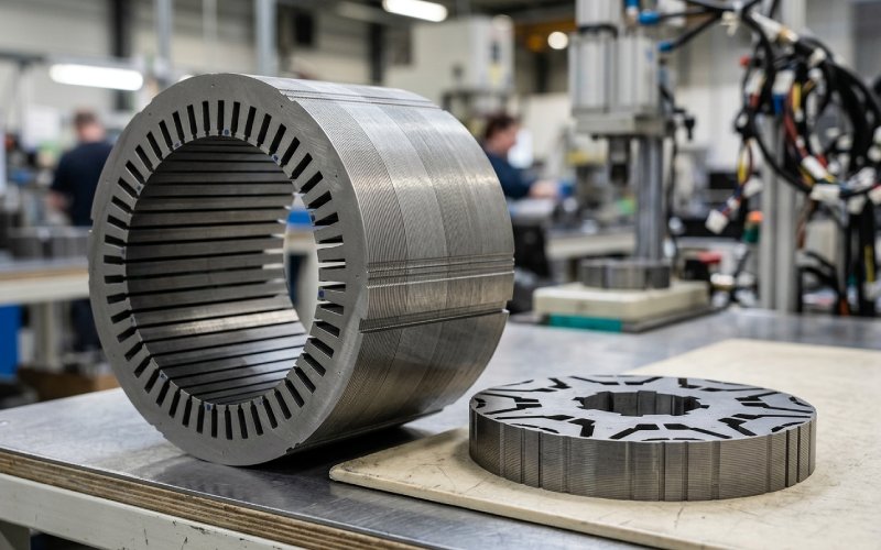
Permanent magnet synchronous motor lamination design usually looks clean in CAD. Then production starts. The weak points show up fast: cut-edge damage, slot features that are too fine for stable stamping, rotor bridges that pass simulation but do not leave enough safety margin after tooling wear, stacks that lose magnetic steel where the model assumed solid iron. That is the real design boundary. Not the drawing. The built part.
In our factory, we do not review PMSM laminations, stator laminations, and rotor laminations as separate topics once a project enters DFM. We review them as one system: steel grade, lamination thickness, punching route, burr limit, joining method, stack compression, and final assembly tolerance. Miss one of those, and the motor may still run. It just will not run the way the original model promised.
Three things decide most failures in lamination release.
First, the electrical steel is no longer ideal after cutting. Punching introduces residual stress and local magnetic degradation near the edge. Second, the stack is not a perfect solid block of active steel. Burr, flatness, coating condition, and joining method all change the real magnetic section. Third, rotor and stator features that look efficient in electromagnetic design can become unstable when stamping tolerance, die wear, and assembly sequence are added.
That is why we treat motor lamination stack design as a manufacturing problem early, not a cleanup step after the magnetic layout is frozen. Stamping, joining, stress-relief annealing, and even final fit-up can change core loss and local behavior enough to move the finished motor away from the simulation baseline.
Thinner laminations help with eddy current loss. Everyone in this field already knows that. The part that gets missed is what happens at the cut edge. The narrower the tooth, rib, or bridge, the more the damaged zone matters because it occupies a larger share of the active section. That is where design starts to drift. Not dramatically at first. Then enough to show up in loss, no-load current, or temperature.
For high-volume motor lamination stamping, punching is still the usual route because it is fast and cost-effective once tooling is established. But punching also brings work hardening, edge deformation, and burr risk. For prototype quantities, laser cutting may look safer because it avoids hard tooling, yet it introduces its own thermal effects and is not a direct stand-in for stamped production behavior. We do not treat prototype-cut laminations as a final answer for a production stamping decision.
Cutting clearance matters. Annealing matters. More importantly, they matter together. Published work on non-oriented electrical steel shows that loss behavior after punching changes with clearance, frequency, and heat treatment, and one test set found the most efficient response around a 3% clearance after annealing under those conditions. We use that the right way: not as a universal number, but as proof that punch setup and post-process recovery cannot be reviewed separately.
In practical DFM, our rule is simple: when the lamination feature is thin enough that the cut-affected zone becomes a meaningful fraction of the section, the geometry is no longer judged only by nominal dimensions. It is judged by manufactured edge condition.
A stator slot is never just a slot. It is a winding access window, a tooth stiffness decision, a local saturation decision, and a noise decision at the same time.
A wider slot opening usually helps winding insertion and production tolerance. It can also make cogging behavior worse. A narrower opening can help the magnetic side, but it pushes the lamination toward tighter stamping control and less forgiving assembly. Then someone adds a small notch to calm cogging torque. Sometimes that works well. Sometimes the notch becomes the first feature to go unstable over die life.
This is where many PMSM articles stay too theoretical. In stamping, the question is not only whether the notch or auxiliary groove reduces ripple. The question is whether the feature survives production with enough repeatability to deliver the same result on batch 1 and batch 100,000. A tooth-tip feature that is too fine, too sharp, or too sensitive to burr will not hold its electromagnetic intent for long.
For stator lamination design, we usually lock these checks before tooling release:
That list sounds ordinary. It is where most expensive revisions begin.
For interior-type PMSM rotors, bridge thickness is usually the hardest line on the drawing. Too thin, and the rotor loses mechanical margin. Too thick, and leakage flux starts taking torque and power factor away. There is no clever wording around that trade. The bridge is carrying two arguments at once.
As speed rises, the bridge stops being a magnetic detail and becomes a structural limit. The same is true for center ribs, outer ribs, and flux-barrier corners. Increasing bridge count or bridge width can improve stress distribution and raise allowable speed, but it also creates more leakage paths. So when a rotor design gets “fixed” late by adding bridge material, it often pays for that fix with electromagnetic output.
We also do not approve rotor corners as sharp analytical geometry. Real stamped laminations need fillet control. Softer transitions reduce stress concentration. They also make the tooling more honest. A bridge that only survives in a sharp-corner model is usually not ready for production review.
A common design-review pattern looks like this: the original rotor bridge is sized from electromagnetic targets, then stamping tolerance, burr, and overspeed margin are added, and the remaining real section is smaller than expected. At that point the design either widens the bridge, changes the barrier shape, or accepts lower magnetic performance. Better to solve that before die steel is cut.
Need a manufacturability check on your PMSM rotor?
Send us your rotor drawing or DXF. We can review bridge width, rib geometry, burr risk, and stacking feasibility before tooling starts.
Skew works. It reduces slotting-related effects, helps with cogging torque, and often improves acoustic behavior. That part is not controversial. The problem is execution. Standard segmented skew can complicate magnet assembly, stack registration, and production control. The skew angle may be right in simulation and still be wrong for manufacturing.
That is why we prefer to discuss skewed rotor lamination stacks in manufacturing terms, not only electromagnetic terms. Step-skew, core-skew, and cross-stacked approaches can all make sense, but only if the stack can be indexed, compressed, and joined without introducing new variation. Some manufacturable skew methods were developed for exactly this reason: keep the ripple benefit, reduce assembly pain.
Our working rule is blunt. If the skew strategy needs exceptional handling to stay aligned, it is not yet production-ready.
Burr is not a cosmetic defect on motor laminations. Burr is a stack behavior problem.
When burr breaks coating isolation between adjacent laminations, interlaminar contact can form. Once that path closes, extra eddy current can circulate and local heating follows. The mechanism is well established. It is also one of the reasons two visually similar stacks can behave very differently under load.
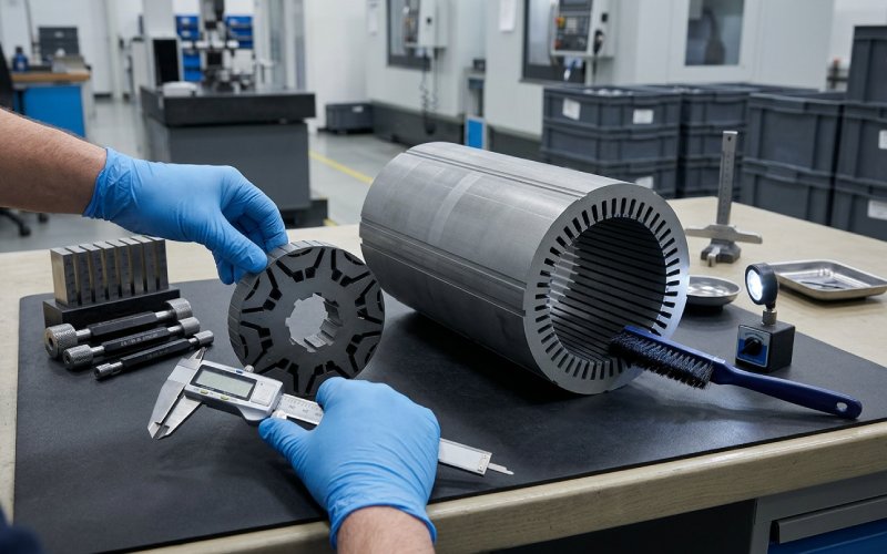
This is why our inspection focus is usually not “does the edge look acceptable?” It is narrower than that. We check whether the burr height, edge rollover, and stack pressure together can create conductive contact across the insulated sheets. A stack with acceptable geometry but poor insulation integrity is still a bad stack.
Another issue. Burr does not only threaten loss. It also affects packing quality and the real active steel per unit stack height. So the stacking factor on the drawing is not an accounting number for us. It is a design parameter. If the motor depends on every bit of back iron or bridge section, the stack density must be defined before release, not measured afterwards as a surprise.
There is no neutral joining method for lamination stacks.
Adhesive bonding tends to preserve insulation better and can be favorable from the magnetic side. Mechanical joining is practical and common, but local deformation and hardness changes can affect magnetic properties. Fusion welding gives robust stack integrity, yet it can damage coating, change local microstructure, and introduce residual stress. All three routes solve one problem while creating another.
So we freeze the joining route early. Not after prototype approval. A welded stator stack, a bonded rotor stack, and an interlocked stack do not behave the same in loss, stiffness, or process repeatability. The wrong sequence here causes the usual late-stage confusion: the parts are dimensionally correct, but the motor is no longer matching the earlier assumptions.
| Design constraint | What it helps | What it can hurt | What we confirm before tooling |
|---|---|---|---|
| Electrical steel thickness | Lower eddy current loss, higher frequency capability | Handling difficulty, cut-edge sensitivity, cost | Steel thickness, production volume, cutting route |
| Slot opening | Winding access, assembly tolerance | Cogging behavior, local tooth stiffness | Minimum winding window and ripple target |
| Tooth-tip notch or auxiliary groove | Cogging torque reduction | Die-life sensitivity, burr concentration, torque drop | Minimum feature size that survives stamping |
| Rotor bridge thickness | Mechanical margin, overspeed safety | Leakage flux, average torque, power factor | Real manufactured bridge section after tolerance and burr |
| Fillet radius at barriers and ribs | Lower stress concentration | Slight flux-path change | Punch-capable radius and stress check |
| Skew or core-skew | Lower torque ripple and noise | Stack registration complexity, assembly cost | Stacking method and angular indexing plan |
| Burr limit | Better insulation integrity, lower short risk | Higher tooling maintenance demand | Inspection method and rejection threshold |
| Joining method | Stack strength and dimensional stability | Local magnetic degradation or process burden | Welding, bonding, or interlocking selected early |
| Stacking factor | Real active steel content | Loss of magnetic section if overestimated | Density target and compression method |
This table is where we spend time during real DFM. Because once tooling is built, changing any one of these usually touches cost, lead time, and yield at the same time.
Before we release a PMSM lamination stack for tooling, we check the following in one review loop:
Working on a new stator or rotor lamination stack?
Share your drawing, target speed, stack length, and annual volume. We can review manufacturability, likely burr-sensitive areas, and joining options before quotation.
Usually it is not one single feature. It is the gap between simulated geometry and stamped geometry. Cut-edge degradation, burr, stack density, and joining method can move performance enough to create loss, ripple, or temperature issues even when the nominal drawing looks correct.
Thin enough to support the target loss and speed range. Not so thin that handling, flatness, edge quality, or cost become unstable for the project volume. Thinner steel is not automatically better once real stamping and stack assembly are included.
Because bridge thickness sits between two hard limits. If it is too small, the rotor loses structural margin. If it is too large, leakage flux rises and electromagnetic output drops. The correct bridge is the one that still works after manufacturing tolerance, burr, and overspeed checks are applied.
Yes. Burr can damage insulation between laminations and create interlaminar conductive contact. That raises local eddy current loss and can create heating inside the stack. It also affects packing quality and the real stacking factor.
Not by itself. Welding is often the right mechanical choice. But it is not magnetically neutral. The weld zone can alter coating integrity, residual stress, and local magnetic behavior. That is why welding has to be selected as part of the design route, not as a late assembly convenience.
Often yes, especially when cogging torque, ripple, or noise are sensitive targets. But the skew method must match the assembly route. A skew concept that is difficult to index or compress consistently can create more production variation than it removes from the electromagnetic side.