Let Sino's Lamination Stacks Empower Your Project!
To speed up your project, you can label Lamination Stacks with details such as tolerance, material, surface finish, whether or not oxidized insulation is required, quantity, and more.
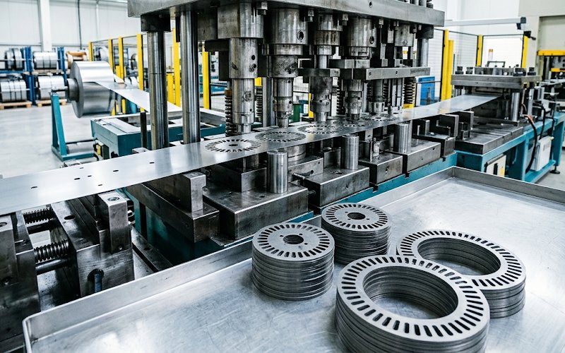
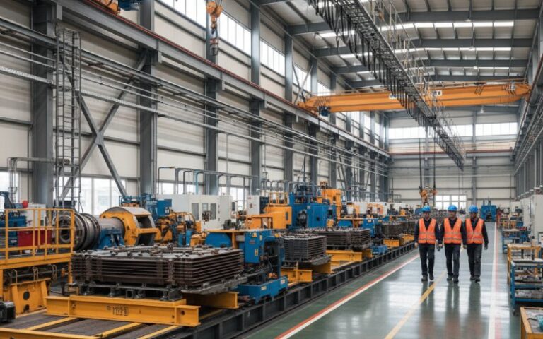
Progressive die stamping for motor laminations is a high-volume manufacturing process that forms lamination profiles through a sequence of stations in one die set, using one controlled strip path to create features, hold registration, and sometimes build partial or finished lamination stacks in-line.
They choose it when the program is stable, the annual volume is real, and the lamination geometry needs to repeat without drifting from station to station, coil to coil, shift to shift. That is where progressive dies start to make sense. And where they stop making sense is just as important.
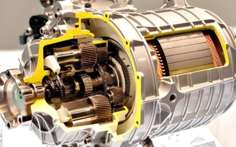
For stator laminations and rotor laminations, progressive dies solve a specific manufacturing problem: too many critical features have to stay in relationship with each other while throughput stays high.
The slot pattern has to stay where it belongs relative to the bore.
The outside profile has to stay where it belongs relative to the slots.
Small bridges. Reliefs. Interlock forms. Pilot features. All of it.
Loose operations can hit the dimensions and still lose the part. That happens. A lamination can look acceptable on a simple check and still build a stack that runs worse than expected because the process controlled size but did not control the feature relationship well enough, or the edge condition got ignored until it became an electrical problem.
So the value of progressive die stamping is not that it makes flat parts quickly. Many processes do that.
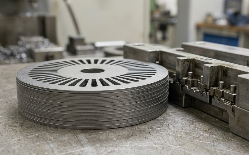
Its value is that it can make motor lamination stacks with repeatable geometry on a repeatable strip path, at production rates that justify serious tooling.
The process starts with electrical steel in coil form. Strip width, grain direction strategy if relevant to the design, carrier logic, scrap balance, feed pitch, and pilot placement all get locked in early. This is not background work. This is where the die starts winning or losing.
A strip layout for laminations has to do several things at once:
The temptation is to optimize scrap first. That is often the wrong instinct.
A strip layout that looks efficient on paper can behave badly in the press. Once the strip begins tipping, lifting, or feeding with small attitude changes, the die starts teaching the part new geometry. Quietly.
The first stations usually create pilot features or other locating conditions that let later stations work from something more reliable than feed length alone. For lamination work, that matters because slot position error compounds badly. A small registration problem does not stay small once it repeats across a stack.
This is one of the reasons progressive dies suit high-volume lamination production. The strip is not being reintroduced from scratch every time. It stays in one manufacturing story from entry to final cut.
This is where the die starts doing the detailed work:
The sequence matters. Very much.
Thin tooth tips, narrow bridges, and dense slot patterns can force a station order that looks odd from the outside. Sometimes a designer leaves material in place longer than expected just to keep the strip alive. Sometimes an empty station is not wasted space. It is breathing room for the process.
That kind of choice rarely shows up in a brochure. It shows up in scrap, die wear, and burr behavior.
The final profile cut is where the lamination leaves the carrier. By this stage, most of the critical geometry has already been established. The last cut is not just a separation event. It is also where force balance, slug control, cut-edge quality, and part release all have to line up at once.
If the last station is unstable, everything upstream starts looking worse than it is. Not because upstream was wrong. Because the part leaves the die badly.
Some lamination programs use in-die interlocking so individual laminations leave the die partially stacked or ready for fast stack assembly. Others stamp loose laminations and join them later by bonding, welding, clamping, or a mixed route.
This is not a minor branch decision. The joining method changes:
Too often the joining method is treated like a secondary assembly choice. It is not. For lamination stacks, it is part of the stamping strategy.
A lot of blog posts on this subject spend too much time on speed. The harder issue is the edge.
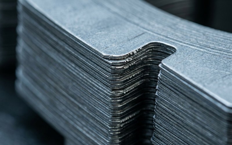
When electrical steel is stamped, the cut edge develops a deformed zone. Clearance, punch sharpness, die wear, material grade, coating condition, and press behavior all affect what that zone looks like. The result is not just a visual difference in sheared edge appearance. It can affect:
That is why burr control in motor laminations should never be filed under cosmetic quality. Burrs can change the electrical behavior of the stack. Not everywhere. Not always. But enough that experienced teams watch burr trend like a process variable, not a cleanup issue.
And once tool wear starts moving the edge condition, the part can remain dimensionally acceptable while performance margin is already being spent.
If the die is running long programs, then wear is part of the product. That sounds blunt. Still true.
Clearance affects fracture behavior and burr formation. Tool wear changes clearance in practice even if the nominal setup never changes. So a progressive die for laminations is not really defined only by its original design. It is defined by the design plus the maintenance discipline that keeps the edge condition inside the intended window.
A few practical consequences follow:
This is the part some teams try to simplify. Usually too much.
Interlocking in lamination stacks is attractive for a reason. It supports automation, improves handling, reduces loose-part management, and can remove a separate stack assembly step. In production terms, it is easy to like.
But interlocks are not neutral features. They disturb local material geometry, can create tighter contact paths between laminations, and may add loss if overused or placed in magnetically sensitive regions.
So the question is not whether interlocking is good or bad. That is a weak question.
The better one is this:
How much interlock is needed to achieve stack stability without creating unnecessary magnetic or electrical penalty?
That answer depends on:
A design that uses interlocks everywhere because the die can form them is usually not an optimized design. It is just an easy design decision made too early.
This process is strongest when the part and the business case both stop moving around.
| Production condition | Fit for progressive die stamping | What usually drives the decision |
|---|---|---|
| Stable, high annual volume | Strong fit | Tooling cost can be spread across long runs, and repeatability becomes more valuable than process flexibility |
| Tight slot-to-bore and feature-to-feature control | Strong fit | One strip path helps hold registration through sequential operations |
| Need for in-die interlocking or fast stack assembly | Strong fit, with caution | Good for throughput and automation, but joining features must be controlled carefully |
| Frequent design changes or early-stage development | Weak fit | Retooling burden rises fast and the process becomes too rigid |
| Very large laminations | Conditional | Tool size, strip economy, and press constraints may push other cutting routes ahead |
| Very thin gauges with poor strip stiffness | Conditional | Possible, but strip handling, lift, and feed stability become harder to protect |
| Small-to-medium laminations with mature geometry | Very strong fit | Good balance of tooling efficiency, strip control, and repeatable output |
In plain terms, progressive dies are best when the program has stopped being experimental.
Progressive die stamping is not the automatic answer for all lamination work.
It starts losing its edge when:
This is where teams sometimes force the die route because the end-state production process is already known. That can be a mistake. A process can be right for SOP and still wrong for early development.
This is the classic one. Burr grows gradually. Inspection still passes the basics. Then stack behavior changes, or assembly friction changes, or local heating shows up later than anyone wanted.
By the time the problem is obvious, the die has often been telling the truth for a while.
A very efficient nest is not impressive if the strip walks, lifts, or feeds inconsistently. Lamination work punishes unstable strip behavior because the error repeats through every station and then repeats again through every part in the stack.
A stack that is easy to move is not automatically a good magnetic stack. Interlock pattern, count, and location need actual engineering review. Not just assembly approval.
Fixed maintenance intervals can be useful. They can also be lazy.
For progressive die stamping for motor laminations, edge quality and burr trend should be tied to maintenance decisions. Otherwise the tooling schedule and the product risk drift apart.
When bonding, welding, interlocking, or annealing decisions are delayed, the stamping route gets boxed in. That tends to create compromises nobody wanted at the beginning and everybody owns at the end.
Do not force a station count reduction if it weakens the strip or overloads a cut condition. A shorter die is not always a better die. Sometimes it is just a denser problem.
Thin bridges, fine teeth, and dense slot regions are less forgiving of edge damage. The smaller the magnetic section, the less room there is to hide stamping effects.
That decision changes feature design, tolerance priorities, handling logic, and inspection strategy. It should not be postponed to “later manufacturing review.”
A lamination can pass isolated dimensions and still produce a weak stack if slot position, bore location, and OD relation drift in combination. For motor laminations, relational accuracy often matters more than isolated nominal accuracy.
Approval data is not enough. Inspection plans should catch drift in:
Stress-relief annealing should be planned, not added as a rescue move after problems appear. If the route needs it, the route needs it from the start.
A cleaner way to evaluate progressive stamping for lamination stacks is to stop asking whether the process is “good” and ask what it trades.
It trades flexibility for repeatability.
It trades upfront tooling cost for lower unit cost at scale.
It trades fast throughput for tighter maintenance demands.
It may trade easy stack handling for extra magnetic penalty when interlocking is pushed too far.
That is the process. A chain of trades. Not a magic answer.
For buyers, sourcing teams, and manufacturing engineers comparing methods for lamination stacks, the decision usually comes down to four filters:
If the answer is yes to most of those, progressive die stamping is usually a serious candidate. If not, forcing it early tends to create expensive lessons.
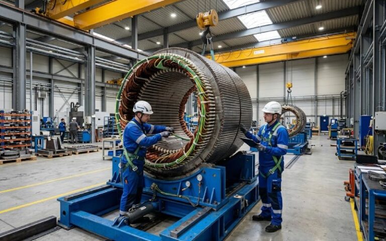
The main advantage is repeatable high-volume production with controlled feature registration. For mature stator and rotor designs, one strip path can hold slot, bore, and profile relationships more consistently than less integrated cutting routes.
No. It works best when the design is stable and production volume is high. For prototypes, changing geometries, or lower-volume programs, a more flexible cutting process may be the better fit.
Because burrs are not only a surface issue. Excessive burr can disturb insulation separation between laminations, increase the risk of local conductive contact, and contribute to loss mechanisms inside the core.
It can reduce performance margin if it is overused or placed poorly. Interlocks help stack handling and automation, but they also disturb the lamination locally. The trade has to be engineered, not assumed.
When the application is sensitive to local magnetic disturbance, when insulation retention is a priority, or when stack integrity needs to be achieved without relying heavily on formed locking features. The right answer depends on the motor design and production route.
Not always. For motor laminations, relative geometry and edge condition often matter as much as nominal dimensional tolerance. A part can measure well and still behave poorly in a stack if the process is damaging the edge or drifting the feature relationship.
No. If the route needs annealing to recover performance after stamping or joining, it should be included in the original manufacturing plan. Using it as a late correction tool usually means the process chain was not defined clearly enough.
Progressive die stamping for motor laminations is at its best when the product is settled, the volume is real, and the team is willing to manage the boring parts properly: strip behavior, edge condition, wear, joining logic, and inspection drift.