Let Sino's Lamination Stacks Empower Your Project!
To speed up your project, you can label Lamination Stacks with details such as tolerance, material, surface finish, whether or not oxidized insulation is required, quantity, and more.
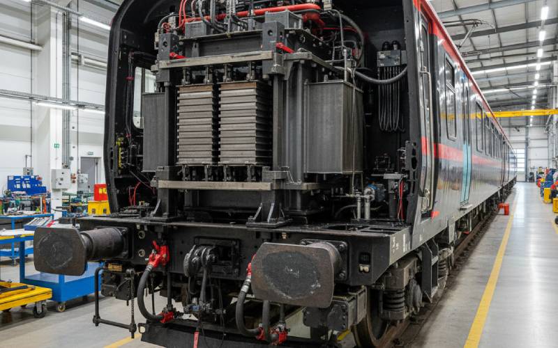
If you stand close to an electric train and listen, you’ll hear a low hum under the noise of doors and announcements. Behind that hum is a traction transformer working very, very hard – and at the heart of that transformer are stacks of thin steel sheets called laminations.
In railway traction duty, those laminations live a rough life: constant vibration, shocks from track joints, violent short-circuit forces, thermal cycling from heavy load patterns, and sometimes brutal climates. Traction transformer brochures talk a lot about efficiency and cooling, but the mechanical robustness of the lamination pack is just as critical for long-term reliability.
Railway traction transformers aren’t sitting on a concrete pad in a calm substation. They’re either bolted to a bogie or chassis (on-board types) or sitting near the track (fixed installations) with frequent short circuits and current shocks.
On-board traction transformers must survive:
Fixed traction transformers under EN 50329 see fewer shocks, but they face frequent short-circuits and current shocks on the catenary or feeder lines.
The big takeaway: in traction service, the lamination pack is constantly being “shaken, squeezed and heated.” If its mechanical design is weak, problems don’t show up in year one – they show up when the fleet is in service and outages hurt.
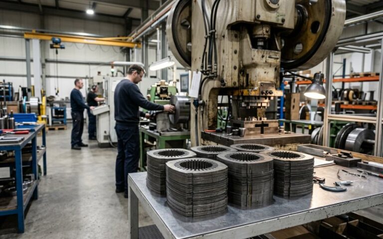
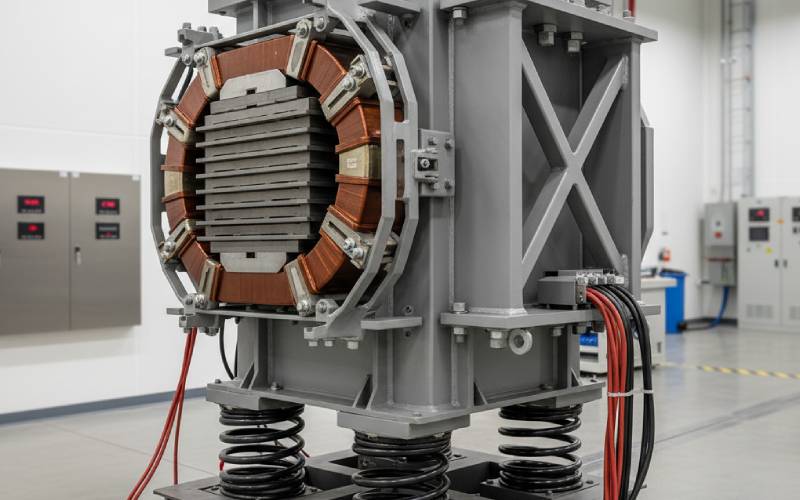
A transformer core is a carefully stacked 3D puzzle of grain-oriented electrical steel sheets, typically 0.23–0.35 mm thick, insulated and built into a frame. Properly designed, the lamination pack does three things at once:
That third role is the one that often gets under-explained. In traction service, you are essentially asking a stack of thin sheets, separated by insulation, to behave like one robust, damped mechanical body for 30–40 years.
If the lamination system is badly designed or assembled, the transformer may still pass type tests – but humming grows, bolts loosen, and in worst cases you start to see insulation wear and internal damage years later.
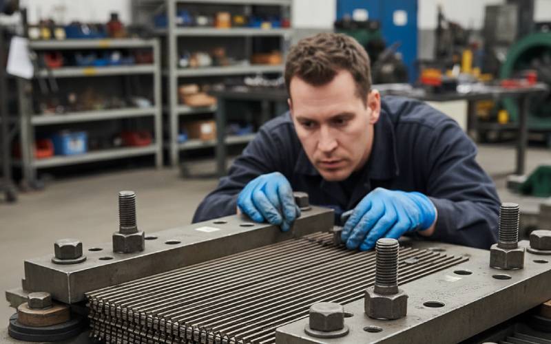
Mechanical failure of laminations rarely looks like a dramatic fracture. Instead, it’s usually a slow, noisy story of loosening, rubbing and shifting under repeated stress.
Over time, small changes add up: varnish cracks, burrs bite, clamp pressure relaxes. What started as a perfectly tight lamination stack becomes a slightly rattling one, and every vibration cycle and short-circuit event makes it worse.
By the time you see serious performance issues, the core has typically gone through thousands or millions of micro-slips between laminations.
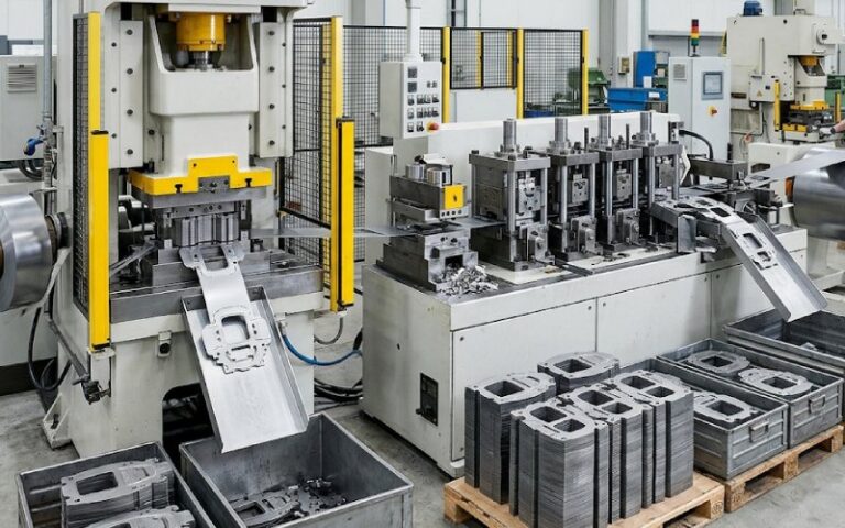
The good news: lamination robustness isn’t magic. It’s the cumulative effect of a dozen design and manufacturing decisions that can be controlled, measured and specified.
From the perspective of mechanical robustness in traction duty, you can think of the lamination system as a tuned mechanical component, not just a magnetic one. That mindset shift alone makes engineers ask better questions about material, geometry and clamping.
The art is in balancing all of this with electrical performance, weight, and cost — especially on board where space and mass limits are ruthless.
A lamination pack in a transformer hung under a high-speed EMU has a very different day-to-day experience than one in a concrete-housed trackside transformer. They’re governed by overlapping but not identical standards (EN 60310 for on-board traction transformers, EN 61373 for shock & vibration, EN 50329 for fixed traction transformers, plus IEC 60076-5 for short-circuit withstand).
Understanding those differences helps you target the right lamination design choices.
| Application type | Main mechanical stresses on laminations | Typical consequences if under-designed | Design focus for lamination robustness |
|---|---|---|---|
| On-board traction transformer (under-frame / roof) | Constant vibration and shocks from track, braking, and coupler impacts; moderate short-circuits; strong thermal cycling. | Progressive loosening of packs, noise increase, fretting at edges, risk of cracks in frames and support brackets. | High vibration damping, robust clamping with fatigue-resistant bolts, carefully tuned friction between laminations, corrosion-resistant coatings, FEM-based vibration mode analysis. |
| Fixed traction transformer (substation / along track) | Frequent high-magnitude short-circuits and current shocks; occasional seismic or handling shocks; moderate vibration. | Local deformation at corners or joints, loosening after severe faults, increased noise, core shift affecting clearances. | Strong yoke and core clamping, carefully calculated short-circuit pre-stress, controlled lamination stacking and burrs, provision for inspection after major faults. |
| Dry-type on-board traction transformer (D-OBTT) | High vibration and shocks plus resin/solid insulation shrinkage and expansion; aggressive thermal cycles due to lightweight designs. | Cracking of resin, debonding between core and support structures, high-frequency noise, reduced mechanical support for windings. | Resin systems with good fatigue behavior, controlled core-resin bonding, lamination design that manages magnetostriction inside rigid encapsulation. |
The core idea: same physics, different emphases. If your fleet is mostly on-board traction units, you almost want to think like an NVH (noise, vibration, harshness) engineer in the automotive world – just at much higher power levels.
Standards rarely say “do your laminations like this,” but they describe stresses and test regimes that laminations must survive as part of the whole transformer.
EN 60310 sets out performance, safety and test methods for traction transformers installed on trains, including requirements that indirectly force robust mechanical design (thermal cycling, overloads, dielectric performance under vibration, etc).
EN 61373 defines shock and vibration test profiles for railway equipment – which on-board transformers must pass as complete assemblies. EN 50329 (fixed traction transformers) explicitly notes that these units are subject to frequent short circuits and current shocks, linking back to IEC 60076-5 for short-circuit withstand.
A transformer that barely passes a short-circuit test or vibration test is not the same as one that comfortably clears the bar with mechanical margins. Robust lamination design is part of building in that margin.
In traction, downtime is expensive and access to equipment can be awkward. That’s why there’s growing interest in using vibration and acoustic signatures to catch problems early, particularly in traction transformers.
Core vibration is now recognized as the major contributor to transformer noise, especially for power and traction units. Magnetostriction of grain-oriented steel drives much of this vibration, and changes in lamination tightness, clamping pressure or material condition show up as distinct changes in the vibration spectrum.
Newer research even explores using dual-attention neural networks on vibration data to identify inter-turn faults in traction transformers at an early stage – the same data streams can help detect lamination-related issues as well.
The practical point: if you’re already collecting vibration data for condition monitoring, use it to track lamination health as well. It’s one of the earliest windows into mechanical degradation.
If you’re a rolling stock OEM, infrastructure owner or procurement engineer, you rarely get to dig into lamination design details – but you can ask smarter questions that push suppliers toward more mechanically robust solutions.
Think of it as taking lamination robustness from “implicit” to “explicit” in your technical specifications and design reviews.
Suppliers who have really thought through lamination robustness can answer these questions clearly and consistently. If the answers are vague or purely marketing-oriented, that’s a red flag.
Rail networks are getting more heavily loaded, with higher speeds, more acceleration, and more power electronics in the loop. That means more harmonic content, more dynamic loads – and more stress on traction transformers and their cores.
Research on transformer magnetostriction, vibration, and noise is moving fast, including improved grain-oriented steels, hybrid core structures and advanced simulation methods for predicting vibration from the microstructure level up to the full transformer.
We’re likely to see:
For now, though, one simple principle holds:
If you treat lamination robustness as a first-class design goal – not an afterthought – your traction transformers will hum quietly, ride smoothly, and stay in service longer than the timetable expects.
And somewhere on a platform, a passenger will still just hear a quiet hum and assume everything “just works” – because you did the hard work on the hidden steel sheets that make it so.