Let Sino's Lamination Stacks Empower Your Project!
To speed up your project, you can label Lamination Stacks with details such as tolerance, material, surface finish, whether or not oxidized insulation is required, quantity, and more.
When you watch a robot arm place a chip on a PCB or a cobot gently hand over a part to a human, you’re really watching a stack of very thin steel sheets doing their job perfectly.
Those sheets — the lamination stack inside the servo motor — quietly decide whether your robot feels silky and safe or jerky and noisy, whether your cobot joint runs cool for 10 years or cooks itself in three. Yet most discussions about robotics and cobots barely mention them at all.
This article is about treating lamination stacks as a first-class design lever in robotics and cobots, not a commodity you order at the end of the project.
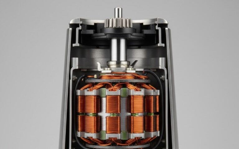
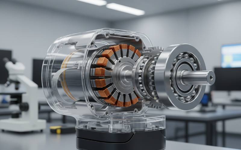
Servo motors are the muscle fibers of robotics: compact, high-torque, and constantly monitored by feedback sensors to hit precise positions and velocities. They close the loop with encoders or resolvers, comparing commanded position with actual position and correcting in real time, which is why they dominate in robots, CNC machines, and automation lines.
For industrial robots, the brief is usually simple: high torque density, speed, and uptime. Cobots, however, add extra constraints: backdrivability, low cogging, low acoustic noise, and inherent safety when bumped into by humans. Those “soft” attributes are deeply influenced by what’s happening inside the magnetic core — the lamination stack — not just by your control software.
Most high-performance servo motors still rely on electrical steel laminations: low-carbon iron alloyed with ~0.5–6.5% silicon, chosen for high permeability and low core loss. These sheets are usually 0.1–1.0 mm thick, punched or cut, then stacked with insulation between them to block eddy currents.
Thinner sheets mean lower eddy current loss at high switching frequencies — an increasingly big deal as servo drives push higher PWM frequencies and as robotic joints go to higher pole counts and speeds. At the same time, going thinner drives up cost and manufacturing complexity, which is why serious lamination suppliers obsess over stamping dies, burrs, and coatings.
| Design lever | Typical range / options | What it does for robotics & cobots |
|---|---|---|
| Sheet thickness | 0.1–1.0 mm (often 0.2–0.35 mm in high-performance motors) | Thinner = lower eddy current loss & cooler operation; thicker = cheaper & stiffer |
| Silicon content in steel | ~0.5–6.5% Si | Higher Si reduces core loss & coercivity, improving efficiency and thermal margin |
| Grain orientation | Non-oriented vs grain-oriented electrical steel | Non-oriented for multi-directional flux in rotating machines; affects performance |
| Stack height | Depends on torque target & geometry | More height = more torque, but more inertia, mass, and thermal load |
| Stacking factor | Ratio of steel to overall stack height | High factor = stronger magnetic path, but sensitive to burrs & coating thickness |
| Insulation coating class | Various C-class coatings / varnishes | Impacts inter-laminar resistance, NVH, and thermal endurance |
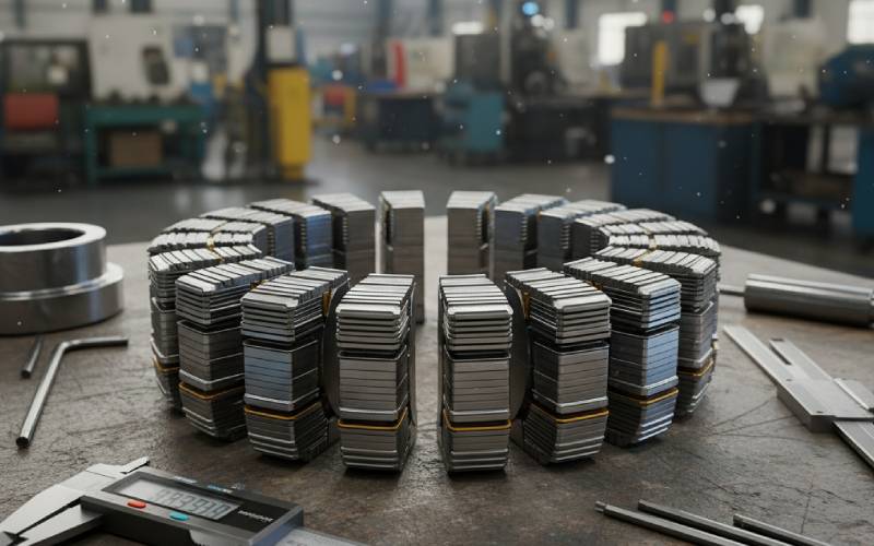
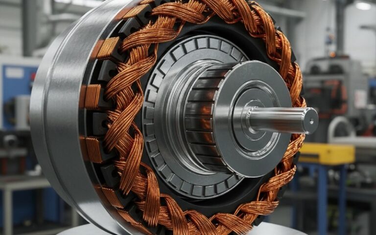
Those hundreds of thin sheets don’t magically stay together. They’re joined using methods such as adhesive bonding, self-bonding (Backlack), mechanical interlocking, riveting/bolting, cleating, and welding.
Research shows a constant tug-of-war: you need mechanical strength and manufacturability, but you don’t want to ruin magnetic performance by damaging insulation or introducing residual stresses and distortion. Glue-based joining tends to maintain low core loss and good insulation, while welding or aggressive mechanical interlocks can increase losses and noise if not carefully controlled.
| Joining method | Electromagnetic impact | Mechanical / manufacturing impact | When it shines in robotics & cobots |
|---|---|---|---|
| Self-bonding (Backlack, full-face bonding) | Excellent insulation, low core loss, low inter-laminar vibration | Requires controlled heat cycle; coating uniformity is critical | High-end servo motors, low-noise cobots, high-speed joints |
| Glue dot / adhesive bonding | Very low additional loss; good NVH; preserves coatings | Extra process steps, curing ovens, careful QC | Precision axes, semiconductor tools, quiet collaborative arms |
| Mechanical interlock (in-die) | Slightly higher losses (local stress & coating damage); scales with number of interlocks | Very cost-effective for mass production; integrates with stamping | High-volume industrial robot motors, cost-sensitive joints |
| Riveting / bolting | Local flux disturbance around holes; manageable for many designs | Great for prototypes or laser-cut laminations; flexible | Prototyping new joint designs, low-volume special robots |
| Cleating / external clamps | Limited impact inside active region if designed correctly | Good structural integrity for large diameters; more hardware | Large direct-drive torque motors, big industrial axes |
| Laser / TIG welding | Can damage coatings and introduce local stress/heat-affected zones, raising loss if uncontrolled | Fast and robust; easy automation; excellent mechanical strength | Heavy-duty servos and traction motors where strength dominates |
If your robot joint feels “notchy” when you backdrive it by hand, you’re feeling cogging torque — parasitic torque that comes from the interaction of permanent magnets with the stator teeth and laminations.
Designers fight this using a mix of electromagnetic design and lamination geometry: adjusting slot/pole combinations, altering magnet shape, changing tooth tip geometry, and skewing the lamination stack. A skewed rotor or stator slightly twists the laminations along the axis so that slotting harmonics “average out” along the stack length, significantly reducing cogging torque and torque ripple with only a small impact on torque constant and efficiency.
An industrial welding robot throwing sparks in a fenced cell has a very different risk profile from a cobot assembling electronics next to a human operator. But inside both, lamination stacks still define the torque, smoothness, and thermal envelope you can work with.
For industrial robots, lamination design tends to prioritize torque density, efficiency, and cost, especially in large volumes. Slightly higher cogging torque can often be tolerated because a gearbox, stiff structure, and clever control loops can hide a lot.
For cobots and exoskeleton-style systems, backdrivability and low apparent impedance are key. High-torque-density joint motors are often paired with low gear ratios or quasi-direct-drive architectures; in that regime, every bit of cogging and friction is amplified into what a human physically feels.
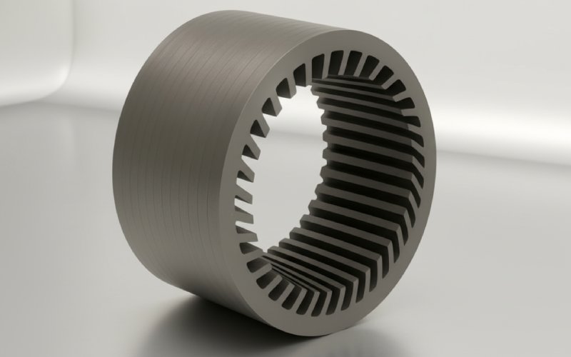
On paper, a lamination stack is just a stack of perfect shapes. On the factory floor, details like burr height, coating robustness, and shaft fit give your motor its actual personality.
High-speed progressive stamping and rapid-stamping presses are the workhorses of lamination production, capable of millions of hits per die. Done right, they deliver tight tolerances and high stacking factors; done carelessly, they leave burrs that pierce insulation, increasing inter-laminar loss and audible noise. Many suppliers complement stamping with laser cutting, single-notching, and rotary notching for prototypes or large diameters, then assemble stacks via interlocking, bonding, or welding in-line.
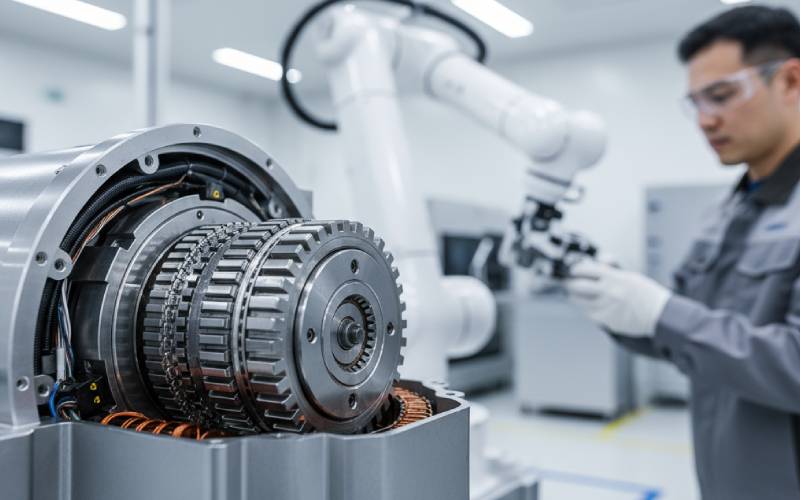
On top of that, inspections — CMM checks, vision systems, iron-loss testers, and Franklin inter-laminar resistance tests — are critical to make sure your simulated motor is the motor you actually get.
While stacked electrical steel is still dominant, there’s a growing push toward soft magnetic composites (SMCs) and axial-flux architectures in high-performance drives, including EVs and robotics. SMCs use insulated iron powder pressed into 3D forms, making it possible to design motors with truly three-dimensional flux paths and simplified assembly compared with traditional laminations.
For robotics and cobots, that opens doors to flatter, pancake-like joints, integrated cooling paths, and topologies that are hard or impossible with simple stacked sheets. However, SMCs bring their own trade-offs in terms of material cost, achievable flux densities, and process maturity, so many designs will continue to rely on carefully optimized lamination stacks for the foreseeable future.
At this point, it’s easy to feel overwhelmed — there are many knobs to turn. To keep it grounded, here’s a human-level design checklist you can walk through the next time you specify a lamination stack for a robotic joint.
If you treat the lamination stack as a strategic component instead of a line item, your robots and cobots will move differently — smoother, quieter, more predictably, and more safely.
And the next time someone raves about how “natural” your cobot joint feels, you’ll know it started with a pile of very thin, very carefully joined pieces of steel.