Let Sino's Lamination Stacks Empower Your Project!
To speed up your project, you can label Lamination Stacks with details such as tolerance, material, surface finish, whether or not oxidized insulation is required, quantity, and more.
Segmented stator and rotor yokes are not a niche curiosity any more; they are what you reach for once torque density, thermal limits, and manufacturability start arguing with each other and you need all three to win at once.
You already know the usual axial-flux story: high torque per mass, short machine, mechanically awkward, thermally stressed. You have seen the clean diagrams of yokeless and segmented armature (YASA) machines and read the sales claims from motor vendors. What tends to be missing is a frank look at how segmentation of both stator and rotor yokes changes the actual constraints you design to, and where the nice diagrams quietly stop matching reality.
This is a working engineer’s view of that gap.
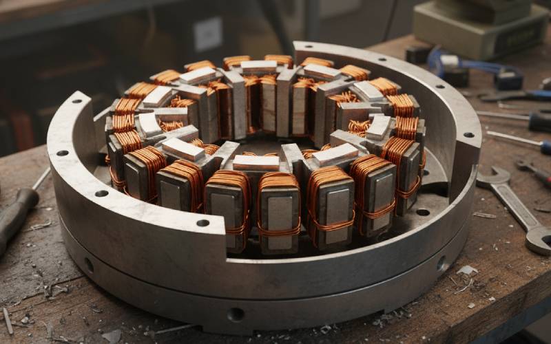
The original YASA work showed that throwing away the continuous stator yoke and replacing it with discrete teeth wrapped in concentrated windings gives you very high copper fill, shorter end-windings, and less iron mass, so torque density shoots up compared with classical torus machines. Modern reviews keep confirming the same pattern: if you are chasing power density, a yokeless or segmented stator is almost always near the top of the short list.
But the more interesting trend in recent papers and patents is that segmentation has moved outside the pure electromagnetic problem.
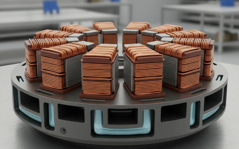
Stator teeth are becoming individual thermomechanical modules, often with their own soft-magnetic-composite (SMC) shoes that touch the cooled housing. Rotor yokes are being broken into circumferential modules with their own back-iron segments and magnet stacks, bolted to a carrier disc for easier assembly and repair. In high-output machines like recent YASA prototypes, the topology is stacked into multi-rotor, multi-stator systems where segmentation is as much about cooling and manufacturing as it is about flux.
So instead of “segmentation increases torque density”, a more honest rule of thumb is: segmentation trades magnetic continuity for control over three other things at once – winding geometry, thermal paths, and how you build or service the motor.
Once you accept that trade, both stator and rotor yokes start to look negotiable.
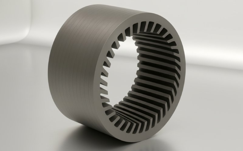
Classical axial-flux stators used a continuous laminated ring with teeth stamped into it. It is electromagnetically clean, structurally stiff, and annoying to wind or cool well. You have done that dance.
The segmented alternatives fall roughly into two buckets.
First, the “true” yokeless segmented armature: separate teeth with coils, carried by a non-magnetic structural disc, with no continuous stator yoke at all. That is the YASA pattern from Oxford and UGent, and it is now well covered in the literature. The teeth see flux only through their own paths to the facing magnets; there is very little circumferential flux sharing between teeth. The price you pay is that the housing and any resin or SMC used for support now become part of the mechanical structure, even though electromagnetically they are mostly out of the picture.
Second, segmented yoke modules that still behave like pieces of a ring. The recent US20230047862A1 patent is a good representative: each stator segment is a laminated core inside an SMC sleeve with pole shoes at each axial end, the shoes contacting a water-jacketed outer case. The laminations give you low core loss; the SMC allows you to sculpt skewed or V-shaped shoes and to push heat directly into the housing. Slot openings between segments can be straight, inclined, Z-shaped, or V-shaped to trim cogging torque and harmonic content without resorting to odd winding layouts.
From a design point of view, the message is simple but slightly uncomfortable.
The “stator yoke” is no longer a single ring you size once from B·t constraints. It is a field of discrete heat sources and flux paths, sitting in a structural and thermal scaffold that you can – and probably should – abuse.
If you treat those segments only as scaled-down versions of a continuous yoke tooth, you will underuse them.
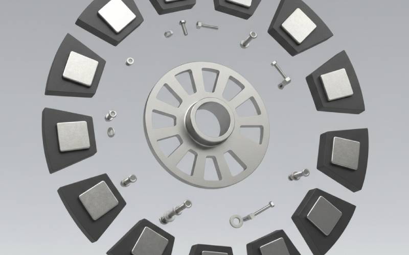
Compared with stators, rotor yokes in axial-flux machines have stayed conservative for longer. Many YASA-style motors still use solid steel discs as rotor yokes with segmented surface magnets or Halbach arrays bonded on. There are good reasons: the rotor carries centrifugal stress, the flux wants a clean return path, and manufacturing likes flat discs.
Patents like CN110945752B show where this is heading next. The rotor is built from circumferential modules: each module has a back-iron segment and a set of magnets with alternating poles, the segment length being less than the full circumference so several modules tile the rotor base.Optional flux guides with extended length or width sit under or beside the magnets to tune saturation and leakage.
Electromagnetically, segmenting the rotor yoke does three main things.
First, it introduces circumferential reluctance modulation. Flux from a tooth now prefers to close through its nearest rotor segment, and there are small “gaps” in the back iron between modules. At low slot/pole combinations, that can be used deliberately as a weak vernier effect or as an extra handle on cogging. At higher pole counts, it mostly becomes another harmonic you have to keep in mind.
Second, it breaks up eddy-current paths in the yoke, which starts to matter once electrical frequency climbs into several hundred hertz and above, or when Halbach structures are used and back-iron flux swings hard. Research on coreless and Halbach AFPM machines keeps highlighting rotor-yoke loss as a non-trivial slice of the budget; segmenting the yoke is one of the cleaner ways to contain that without exotic materials.
Third, it makes the rotor a kit. Swap modules, change pole count, or replace damaged magnet packs without scrapping a full disc. That sounds like a production engineer’s concern, but it back-propagates into the electromagnetic design because you can experiment more aggressively with pole-arc ratios and magnet shapes when the result is “change a module drawing” instead of “redesign a 600 mm rotor disc”.
The mechanical risk is obvious: more joints, more bolts, more tolerance chains. But if you are already designing a stator made of twenty or thirty composites-and-copper modules, treating the rotor as sacred and monolithic is sometimes just inertia.
Once both sides of the airgap are chopped into modules, the pattern of those cuts matters as much as the slot/pole combination you proudly optimized.
A few practical observations, skipping the extended derivations you already know how to write.
If stator-tooth pitch and rotor-segment pitch share a low common multiple, you get distinct circumferential “hot spots” in tooth flux density. The local B peaks where rotor gaps and tooth centers line up multiply. That can be useful if you want a bit of field modulation, but usually it shows up as uneven tooth saturation and torque ripple at one particular eccentricity harmonic.
If you stagger rotor segments by a half-tooth or some other fraction, you effectively get circumferential skew without tilting any magnet. Several modular-rotor patents hint at this by allowing multiple module lengths and optional offset patterns; no formula is given, but the idea is clear enough. Combined with V- or Z-shaped stator slots from the segmented-core patent, you can get much of the cogging-torque reduction of classical skew with tooling that is easier to stamp or press.
If both sides are segmented and both support some kind of skew, you need to make a conscious decision about which one “owns” cogging reduction. Splitting the responsibility randomly tends to produce a machine that simulates well under perfect geometry but is very sensitive to assembly spread, because the delicately balanced cancellation assumes exact angular relationships between modules.
One useful mental shortcut is to assign roles. Let the stator segmentation handle copper, cooling, and most of the cogging work; let the rotor segmentation handle magnet packaging, yoke losses, and manufacturability. That does not give you a closed-form optimum, but it keeps you from chasing ghost harmonics.
The table below compresses what designers are actually doing today, rather than what idealized sketches suggest.
| Aspect | Continuous stator & rotor yokes | Segmented stator, solid rotor yoke (YASA-type) | Segmented stator and modular rotor yokes |
|---|---|---|---|
| Typical use cases | Industrial AFPM, low volume, moderate torque density | EV traction, aviation demonstrators, high torque density machines | Modular drives, pumps/blowers, high-variant products, aggressive prototype work |
| Torque density potential | Good, limited by long end windings and larger iron mass | Very high due to concentrated windings, reduced stator iron, double-rotor options | Similar or higher than YASA-type if rotor losses and mechanical limits are controlled |
| Core and magnet losses | Relatively easy to predict; continuous yokes support smooth flux | Stator core losses localized to teeth; magnet eddy-current losses can dominate if not segmented | Rotor-yoke eddy currents reduced by segmentation; extra leakage risk between modules |
| Thermal path | Iron ring to housing; winding cooling often indirect | Teeth or SMC shoes into housing, plus housing water/oil cooling and sometimes heat pipes | Both stator segments and rotor modules can be tied into cooled carriers; more design knobs, more local gradients |
| Manufacturing | Simple laminations; winding and assembly can be labor-intensive | Teeth wound individually, then potted or clamped; good for automation but tooling is specialized | Rotor and stator built from repeatable modules; flexible for variants, but assembly tolerances and process control are demanding |
| Service and variants | Entire stator or rotor usually replaced as a unit | Stator teeth replaceable with effort; rotor usually one piece | Individual modules can be swapped; pole counts and diameters can be changed by module count and carrier geometry |
| NVH and torque ripple | Dominated by slot/pole choice and magnet shape | Additional spatial harmonics from segmented teeth; mitigated with magnet and slot shaping | Harmonics from both stator and rotor segmentation; needs deliberate phase management between patterns |
You could argue for a fourth column with coreless axial-flux machines, but those live in a slightly different design space and mostly sidestep the yoke discussion altogether.
Some habits from continuous-yoke thinking subtly mislead you once you move to segmented stators and modular rotors.
Treating the stator support as “mechanical only” is one of them. In segmented stator designs, the structural path from tooth to housing often runs through SMC shoes, resin, or a thin steel ring. That path sets not just mechanical stiffness but also the thermal time constant of each tooth. The patent using SMC sleeves explicitly exploits this: SMC provides both magnetic conduction where needed and a controllable thermal bridge into a water-jacketed case. Ignoring that coupling gives you simulations that are right for two seconds and wrong for the rest of the duty cycle.
Another habit is sizing rotor back-iron as if it were a uniform ring. In modular rotors, the effective cross-section for flux is a periodic function of angle; some modules might carry more flux than others if the stator layout, pole-arc, and module borders align badly. A simple way to catch this early is to run a 2D circumferential reluctance network in which each rotor module has its own back-iron element and see how flux distributes with a few slot/pole combinations. That model will not win any awards, but it will flag ugly patterns before you have invested time in 3D FEA meshes.
A third habit: over-relying on magnet skew for torque-ripple control. Segmented stator patents now give you shaped slot openings, skewed shoes, and even Z-shaped paths, all baked into the tooth geometry. Combined with rotor segmentation, you can often keep magnets simple and mechanically robust while shifting most ripple control into static iron. That simplifies magnet sourcing and assembly, which matters more when you move toward the production volumes that YASA, Mercedes, and others are talking about.
The recent record-class axial-flux motors are not succeeding because someone found a magical new magnet. They are leaning hard on topology and cooling, and segmentation of stator and rotor yokes is baked into both.
YASA’s current prototypes, for example, report power densities over 40 kW/kg, with later units reaching claims around 59 kW/kg, at current densities that would look aggressive in a traditional industrial catalogue. Independent analyses that reconstruct the geometry from photos and typical material data reach the same conclusion: stacking multiple yokeless stages and cooling them very directly is what makes the numbers plausible.
Once stator teeth are separate modules, you can edge-wind copper tightly around each one, leave controlled gaps for oil or coolant, and feed heat straight into a cooled housing. With SMC shoes or heat pipes between teeth and housing, as in recent MDPI work, the thermal path becomes short enough that 40–60 A/mm² in the copper is survivable for significant duty cycles, provided you are honest about your temperature rise budget.
Rotor segmentation helps here as well. Breaking the back iron and magnet stacks into modules gives you more surface area and more options to route cooling oil or gas through the rotor carrier, and it limits the eddy-current loss density that would otherwise turn a smooth rotor disc into a heater at high frequency. For very high tip speeds, you can even consider different materials for different modules, trading saturation margin against mechanical strength on a per-module basis instead of for the whole disc.
The net effect is that current density and thermal limits are no longer dictated primarily by the worst-cooled region of a continuous yoke. Segmentation lets you bias cooling capacity where losses are highest. That is a quiet but serious shift.
The research pipeline is already full of variants that push segmentation in new directions: segmented teeth with separate inner and outer portions to fix radial flux-density imbalance, hybrid axial–radial flux machines with SMC modular stators, and multi-stack ironless designs intended for aircraft propulsion. Comparative studies keep finding that yokeless and segmented armature structures beat more conventional axial-flux layouts on torque density and often on efficiency, once you accept the manufacturing complexity.
On the industrial side, YASA’s motors are moving from concept cars into series production with Mercedes, Lamborghini, Ferrari and others, and the public patents show stator and rotor modularity becoming more pronounced, not less. For smaller and mid-power machines, modular rotor and stator kits described in CN110945752B and related filings hint at families of products where pole count and diameter are just configuration parameters rather than new part numbers.
So if you are working on axial flux today, it is reasonable to assume that “continuous yoke, simple disc rotor” will slowly become the baseline for conservative designs, not the upper limit of what is practical.
If you stay with monolithic yokes, you get simpler models and simpler tooling, and you will still build respectable axial-flux machines. If you accept segmented stator and rotor yokes, you get a messier design space, but also finer control over copper geometry, thermal paths, and manufacturability.
The evidence from recent research and from the motors now quietly entering production is that this mess is worth dealing with.