Let Sino's Lamination Stacks Empower Your Project!

To speed up your project, you can label Lamination Stacks with details such as tolerance, material, surface finish, whether or not oxidized insulation is required, quantity, and more.

Sensitivity Analysis: Tooth-Tip Radius and Slot Opening on Losses

Designers love adding poles, tweaking magnets, or changing control strategies. But two of the quietest, highest-leverage knobs in a slotted electrical machine are purely geometric:

  • the tooth-tip radius, and
  • the slot opening.

They live in the millimeter range, yet they shape the air-gap flux waveform, loss distribution, torque ripple, and even noise. Papers on stator core shaping and slot design show that careful tuning of these tiny features can shift iron losses by tens of percent and change magnetic noise dramatically.

Most blog posts treat them as a line in a CAD screenshot. Let’s not do that.


  • What you’ll get from this article
    • Intuitive picture of how tooth-tip radius and slot opening influence flux and losses
    • Connection to the main iron-loss mechanisms (hysteresis, eddy, excess)
    • Lessons distilled from recent literature on slot opening and tooth shaping
    • A practical workflow to run your own sensitivity analysis
    • A rule-of-thumb matrix (table) you can keep next to your FEA tool

1. Where tooth-tip radius and slot opening live in the design space

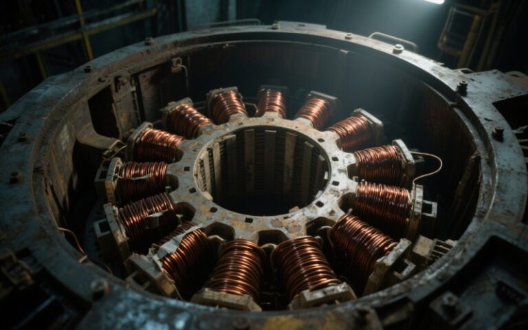
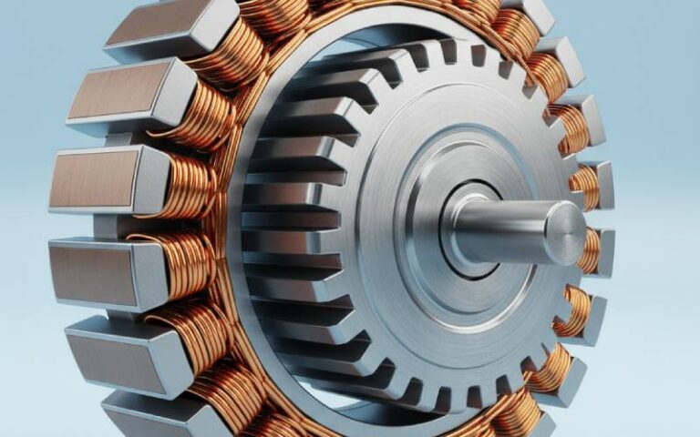
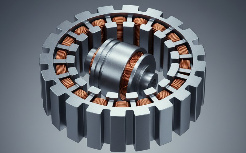
Picture a stator tooth: a tall beam of laminated steel, necking down into a narrow tooth top that faces the rotor. The tooth-tip radius is the rounding at the inner corners, where the tooth meets the air-gap. The slot opening is the gap between neighboring tooth tips.

Those two dimensions sit right where everything happens:

  • the air-gap flux squeezes through,
  • slot harmonics are born,
  • conductors near the slot top see leakage flux,
  • mechanical tolerances bite hardest.

Manufacturing houses that specialize in electrical steel laminations explicitly call out slot opening, tooth tip radius, and bridge width as primary dimensions to control because they directly influence air-gap flux, harmonic content, losses, and noise.


  • At a high level, these two dimensions mainly control
    • Permeance waveform in the air-gap → slot harmonics, cogging, torque ripple
    • Local flux density peaks at tooth corners and tooth top → iron loss “hot spots”
    • Leakage and fringing fields into the slots → AC copper losses in the end-region and slot conductors
    • Mechanical & acoustic behavior → vibrations and magnetic noise linked to slot opening ratios

2. Loss mechanisms that care about these dimensions

Before we tweak geometry, it’s worth revisiting what we’re actually trying to move: loss components. In any slotted PM or induction machine, efficiency is primarily eaten by:

  • copper loss,
  • core (iron) loss,
  • mechanical loss,
  • stray/magnet/AC winding losses.

Tooth-tip radius and slot opening are mainly iron-loss and AC-loss knobs, not copper-I²R knobs. Modern iron-loss models typically decompose core loss into three parts — hysteresis, classical eddy current, and an “excess” or anomalous component that captures local high-frequency microscale effects.

Detailed mapping studies on high-speed PM machines show that stator yoke and teeth dominate total core loss, with the tooth top being especially sensitive to changes in load and flux pattern. Under some conditions, the tooth-top loss growth with load is hundreds of percent larger than that in the yoke.

That is exactly the region tooth-tip radius and slot opening reshape.


  • Core-loss components most affected by tip radius & slot opening
    • Hysteresis loss: depends on local B-H loop area; sharp corners and flux “crowding” increase it.
    • Eddy current loss: grows with frequency and (B_{pk}^2); slot harmonics and high local flux at tooth tips feed it.
    • Excess (anomalous) loss: driven by fast local flux variations, particularly where slotting distorts the field.
    • AC copper / proximity loss: higher when conductors sit near the slot opening where leakage flux is strongest.

close-up of stator teeth

3. Tooth-tip radius: sensitivity and intuition

Start with the tooth tip radius ( R_t ). Imagine shrinking it towards zero: you get a very sharp tooth corner. Flux lines in the tooth want to spread into the air gap; a sharp corner forces them through a tight “bottleneck,” creating flux crowding and local saturation at the tooth top.

Studies on stator core shaping show that introducing suitable radii at tooth corners (often discussed at the root, but the same intuition applies to the top) can noticeably reduce local core losses by easing those peak flux densities.

On the other hand, if you over-round the tooth tip, you’re effectively widening the air gap locally:

  • The main air-gap flux sees higher reluctance,
  • magnets or rotor currents must “work harder” for the same torque,
  • flux in the tooth top may drop (good for local iron loss) but torque density suffers.

Sensitivity analyses on tooth-coil PMSMs, where tooth-tip dimensions are swept, show exactly this trade-off: torque density is strongly influenced by tooth tip width/radius, but there is a diminishing returns region where further rounding spoils torque for modest loss gains.

The “sweet spot” is usually a moderate radius: large enough to avoid corner saturation and to soften flux gradients, small enough to keep decent permeance and flux focusing.


  • Rules of thumb for tooth-tip radius sensitivity
    • Too sharp (small radius)
      • High local (B) at corners → tooth-top loss hotspots and potentially more excess loss.
      • Stronger slotting effects → more slot harmonics and cogging torque.
    • Moderate radius (often optimal)
      • Reduces corner saturation and distributes flux more evenly along the tooth top.
      • Usually small penalty in torque while improving iron-loss “hotspot” behavior.
    • Too large radius
      • Acts like a locally larger air gap → reduced flux linkage, lower torque/EMF.
      • May help core losses, but often not enough to justify the torque hit unless you’re ultra efficiency-driven.

4. Slot opening: sensitivity and intuition

The slot opening ( b_{so} ) is the clear distance between tooth tips at the air-gap. It has a complicated relationship with losses because it reshapes the permeance waveform around the air-gap.

Historically, open slots were known to introduce extra loss even in simple test cores; classic work in the 1930s already pointed out that losses due to open slots must be separated from “true” iron loss when characterizing materials.

More recent research is clearer:

  • For induction machines, a semi-analytical model plus measurements showed that adjusting stator and rotor slot openings can reduce the harmonic component of iron losses by about 30%, by cancelling certain slotting-related flux density harmonics.
  • In synchronous machines, increasing stator slot openings tends to reduce stator core losses (because flux is more spread out in the teeth), but at the cost of lower torque and sometimes higher rotor losses and torque ripple.
  • For axial-flux machines, larger slot openings increase the reluctance in tooth tips and substantially decrease air-gap flux, especially under load where armature reaction is strong.

And then there’s the winding: as conductors move closer to the slot opening—where leakage and fringing fields are larger—AC losses increase significantly.

So slot opening pulls on at least four strings: iron loss, torque, AC loss, and noise.


  • Slot opening trade-offs (qualitative)
    • Wider slot opening
      • Flatter permeance waveform → lower tooth saturation and sometimes less stator tooth iron loss.
      • Stronger slot harmonics → more torque ripple & possible magnetic noise.
      • Increased reluctance at tooth tips → lower torque/EMF, especially pronounced in axial-flux and high-speed machines.
      • Conductor nearer to slot top → more AC copper loss if you pack the slot aggressively.
    • Narrower slot opening
      • Stronger flux focusing → higher torque density but higher tooth-top flux and losses.
      • Reduced slot harmonics → smoother torque, potentially lower magnetic noise.
      • Tighter window for winding insertion and higher manufacturing difficulty.

5. A practical workflow for sensitivity analysis

You can treat tooth-tip radius and slot opening as just two more design parameters in a parametric optimization, but they behave differently from global quantities like stack length or magnet thickness. They mostly affect field quality and local loss distribution, not just bulk performance.

Good news: that makes them perfect targets for a focused sensitivity analysis.

In practice you’ll combine 2D/3D FEA with an iron-loss model (Bertotti-type or improved variants) and possibly an AC winding-loss model.


  • Step-by-step sensitivity workflow
    • 1. Fix a credible baseline machine.
      • Use a design that already meets torque/speed constraints and satisfies thermal limits.
    • 2. Define normalized parameters.
      • E.g. ( \hat{R}t = R_t / R{si} ) (tooth-tip radius over stator inner radius), ( \hat{b}{so} = b{so} / \tau_{slot} ) (slot opening over slot pitch).
    • 3. Choose a small design of experiments (DoE).
      • For each of ( \hat{R}t ) and ( \hat{b}{so} ), pick 3–5 levels (e.g. sharp, baseline, moderate, large).
      • Keep other geometry fixed to isolate effects.
    • 4. Run FEA for relevant operating points.
      • No-load, rated load, and 1.1× rated load are common because tooth-top and tooth-body losses respond differently with load.
    • 5. Post-process field data into loss maps.
      • Use per-region integration (tooth top, tooth body, tooth root, yoke, rotor) rather than just total core loss.
    • 6. Compute sensitivity metrics.
      • Finite-difference sensitivities like (\partial P{iron, tooth} / \partial \hat{R}t), (\partial P{iron, yoke} / \partial \hat{b}{so}).
      • Track torque, EMF, torque ripple, and AC copper loss alongside.
    • 7. Fit simple response surfaces.
      • Even quadratic fits in ( \hat{R}t ) and ( \hat{b}{so} ) give useful trends for optimization loops.
    • 8. Pick an operating-point-weighted optimum.
      • For example, minimize a weighted sum of stator tooth-top iron loss, AC copper loss, and torque ripple subject to torque ≥ target.

engineer analyzing motor losses

6. A rule-of-thumb matrix from literature-backed patterns

To make the trade-offs more concrete, the table below summarizes qualitative effects of changing tooth-tip radius and slot opening, combining trends seen across several machine types.

⚠️ The table is intentionally qualitative. Exact sensitivities are machine-dependent—slot/pole combinations, magnet type, speed, and material all matter.

Design changePrimary effect on flux & harmonicsTypical impact on losses (qualitative)Other side-effects / notes
Slight increase in tooth-tip radiusSmooths flux at tooth corners, marginally higher local air-gap reluctance↓ Tooth-top iron loss hotspots; ≈ Yoke loss; small or neutral effect on total stator iron lossOften “free” from torque viewpoint if radius is modest
Large increase in tooth-tip radiusSignificantly weaker flux focusing at tooth top↓ Tooth-top iron loss; may ↓ overall stator iron loss but not proportionally to torque reductionNoticeable torque / EMF drop; may reduce cogging slightly
Decrease in tooth-tip radius (sharper corner)Stronger flux crowding at tooth inner corners↑ Tooth-top iron loss strongly; potential ↑ in excess loss due to steep local gradientsMay boost torque a bit; worse for NVH and hotspot temperatures
Widen slot opening (slot area ≈ constant)Flatter permeance waveform, higher reluctance in tips, stronger slot harmonicsOften ↓ stator tooth core loss; possible ↑ rotor or stray loss; ↑ AC copper loss near slot top if conductors are closeCan increase torque ripple and magnetic noise
Narrow slot opening (slot area ≈ constant)Stronger flux focusing, reduced slot harmonics↑ Tooth-top iron loss (higher local B); yoke loss may change little; ↓ slot-harmonic-driven iron loss in some machinesGood for torque density, but winding insertion is harder
Move conductors closer to slot opening at fixed openingHigher leakage field through conductors↑ AC copper loss and strand heating, especially at high frequency or PWM supplySometimes done for thermal/mechanical reasons—needs checking

You’ll see echoes of these trends in detailed studies of stator core loss distribution, where tooth-top losses are the most sensitive to changes in field pattern and load.


  • How to use this table in practice
    • When iron losses are too high in the tooth top region, try a modest increase in tooth-tip radius or a slightly wider slot opening and verify torque impact.
    • When torque ripple / noise is the main issue, consider narrowing the slot opening a bit and possibly redefining the tooth-tip shape to reduce slot harmonics.
    • When AC winding losses dominate (high-frequency or inverter-fed machines), prioritize slot opening and conductor placement, even if core loss looks acceptable.

7. Bridging analysis and manufacturing reality

All of this beautiful sensitivity analysis assumes the machine you build actually matches the geometry you simulated.

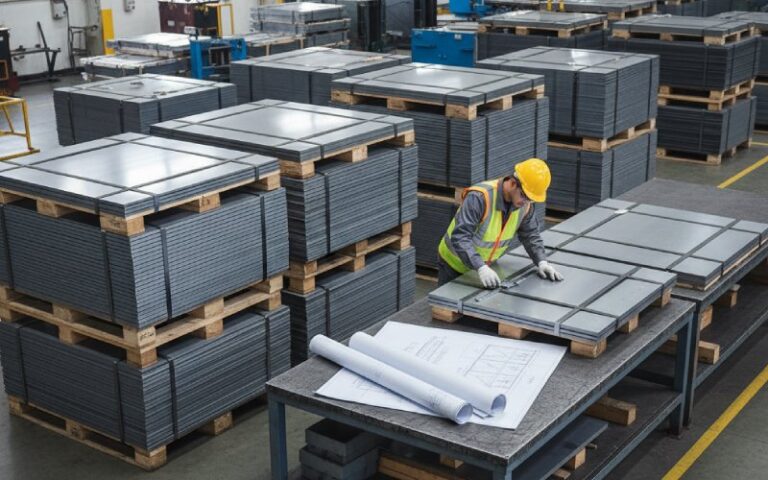
In reality, tooling and stamping tolerances smear out tooth-tip radius and slot opening. Lamination suppliers highlight that tight die tolerances are essential to keep slot opening, tooth-tip radius, and bridge widths within design targets; otherwise, losses and noise drift away from the predicted values.

Sensitivity studies on stator geometries also show that unequal tooth widths or small deviations in tooth geometry can shift flux linkage and winding factor enough to change both torque and loss distribution.

If you’re pushing efficiency to 95–98%, sloppy control of a 0.1–0.2 mm slot-opening tolerance can erase weeks of FEA optimization.


  • Design & manufacturing checklist
    • Annotate tolerances in the CAD model for tooth-tip radius and slot opening, not just nominal values.
    • Ask your lamination supplier what practical tolerance bands are achievable and feed those into a “worst-case” sensitivity sweep.
    • Include tolerance variation in your DoE: simulate ± tolerance on (Rt) and (b{so}) to see if losses or torque ripple blow up.
    • Check for assembly deformation (shrink-fit, welding, potting) that may effectively change slot opening at operating temperature.
    • Measure back-EMF, iron loss, and NVH on prototypes and compare not only to nominal design but to the sensitivity envelopes.

8. Wrapping up: thinking like the flux

If you mentally “follow the flux,” tooth-tip radius and slot opening stop being just dimensions and start feeling like tuning knobs for how hard the steel has to work.

  • Tooth-tip radius mainly decides how gently you let flux enter and leave the tooth top.
  • Slot opening mainly decides how much the air-gap permeance rocks back and forth as the rotor moves.

Literature across induction, radial-flux, and axial-flux PM machines shows that:

  • Optimized slot openings can cut harmonic iron losses by around a third in some designs.
  • Careful tooth-corner shaping can significantly relieve local tooth and yoke losses without exotic materials.

Your job as a designer is to decide where to spend and where to save:

  • spend some torque to buy lower hotspots and easier cooling,
  • or spend some manufacturing complexity to buy smoother torque and quieter operation.

A structured sensitivity analysis, focused just on tooth-tip radius and slot opening, gives you that trade-off map instead of relying on hunches. Once you have that map, every future machine you design benefits—because these two tiny dimensions quietly touch almost every loss mechanism that matters.

Share your love
Charlie
Charlie

Cheney is a dedicated Senior Application Engineer at Sino, with a strong passion for precision manufacturing. He holds a background in Mechanical Engineering and possesses extensive hands-on manufacturing experience. At Sino, Cheney focuses on optimizing lamination stack manufacturing processes and applying innovative techniques to achieve high-quality lamination stack products.

New Product Brochure

Please enter your email address below and we will send you the latest brochure!

en_USEnglish

Let Sino's Lamination Stacks Empower Your Project!

To speed up your project, you can label Lamination Stacks with details such as tolerance, material, surface finish, whether or not oxidized insulation is required, quantity, and more.