Let Sino's Lamination Stacks Empower Your Project!
To speed up your project, you can label Lamination Stacks with details such as tolerance, material, surface finish, whether or not oxidized insulation is required, quantity, and more.
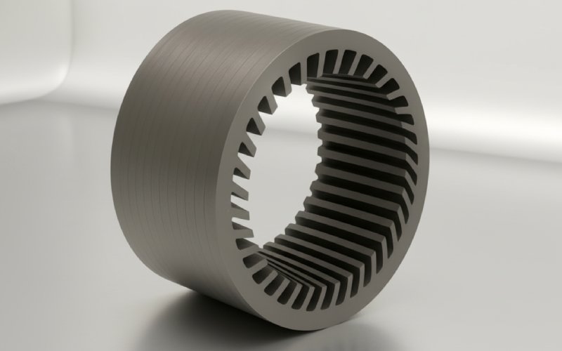
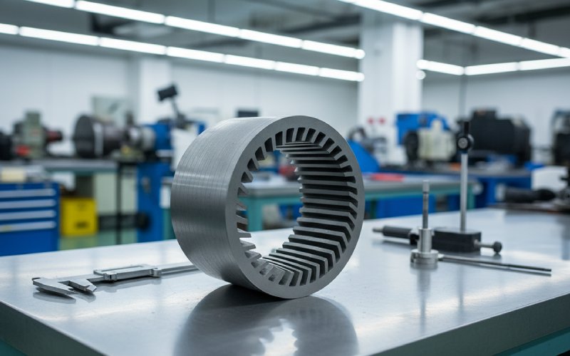
In rotor lamination stacks, skew is not a cosmetic angle. It is a phase tool.
When a straight rotor stack lets every axial slice meet the same slotting event at the same instant, the ripple peaks add. Cleanly. Too cleanly. Skew breaks that alignment along the stack length, so the local torque disturbances stop arriving in phase. The average torque stays. Much of the roughness does not. That basic effect is why one-slot-pitch skew keeps showing up in serious motor work: it can leave the fundamental almost unchanged while cutting the slot-related content much harder. One analytical study put the fundamental skew factor at about 0.995 for a one-slot-pitch skew, while the first slot harmonic dropped to roughly 7% in the same framework.
That is the torque side.
The noise side is close, but not identical. Electromagnetic noise is driven less by average torque and more by force waves, especially radial force content that finds a structural path into the housing. Once the rotor laminations are skewed, those force waves are redistributed along the axial direction instead of stacking up in one circumferential pattern. The machine still produces force. It just stops producing the same force pattern, in the same place, at the same time, along the full core length. That matters. Recent vibration studies on both permanent-magnet and induction machines tie skew directly to lower torque harmonics, weaker problematic force-wave components, and lower vibration or noise when the skew angle is selected with the electromagnetic spectrum in mind.
A skewed rotor lamination stack is an axial averaging device. That is the shortest accurate description.
Each lamination, or each stack segment in a step-skew build, is rotated by a small angular increment. So the tooth-slot alignment seen at one axial position is offset from the alignment seen a few millimeters away. Local reluctance variation is still there. Slotting is still there. Cogging sources are still there. They are just phase-shifted along the stack, which weakens the summed disturbance seen at the shaft and the housing.
That is why skew usually feels more effective than its geometry looks. A few degrees. Sometimes less. Yet the air-gap interaction changes enough to soften low-speed notchiness, flatten ripple peaks, and calm the acoustic signature. Usually not by magic. By cancellation.
And no, continuous skew is not the only useful form. In production lamination stacks, step-skew is often the practical route because it approximates the same averaging effect with discrete axial segments. Continuous skew is basically the limiting case of step-skew with the segment count pushed very high. The electromagnetic intent is the same; the manufacturing route is not.
The obvious answer is “harmonic cancellation.” Correct, but too broad.
What matters in real rotor lamination stacks is which harmonics you are asking skew to punish, and what you are willing to pay for that punishment. A small skew can weaken slot harmonics strongly while barely touching the main working field. Increase the skew too far and the main torque-producing component starts to give something back. That trade-off is not theoretical. It shows up in measured torque, starting behavior, maximum torque, and back-EMF shape. Studies on different machine families keep landing in the same region: around one stator slot pitch is often a practical first target because ripple reduction is meaningful while the average torque penalty can remain small. A classic result reported less than 2% average torque drop at one slot pitch in one reluctance machine set, while larger skews pushed the penalty much higher. Induction-machine work also shows that as skew angle grows, starting torque and maximum torque trend downward even while vibration-related harmonics improve.
So the better question is not “does skew reduce torque ripple?” It does. The better question is: which ripple components are dominant in this stack, and how much fundamental are we willing to dilute to cancel them?
That is where lamination-stack engineering stops being generic. Slot count, pole count, air-gap sensitivity, saturation level, control strategy, and load point all matter. Even the same rotor topology can want a different skew decision once the load spectrum shifts. Recent work on optimal skew angles under varying load supports that point directly: skew effectiveness is load-dependent, and saturation changes the answer.
Noise drops for two reasons. One direct. One indirect.
The direct reason is that skew weakens force-wave components that would otherwise excite the stator and housing more aggressively. In induction-machine analysis, the radial electromagnetic force distribution changes along the axial direction once skew is introduced. In permanent-magnet machine studies, rotor-step skewing suppresses the force content that feeds electromagnetic vibration and noise. That is the structural path.
The indirect reason is that lower cogging and lower torque ripple reduce the secondary vibration problems that show up at low speed, during transitions, and near resonant operating bands. One recent traction-motor study using a two-step skew reported about 91.6% cogging-torque reduction, with vibration velocity reductions around 51.9% at rated speed and 68.7% at maximum speed, though those numbers are geometry-specific and should never be copied blindly into a new design. The pattern is the useful part: when skew is tuned around the dominant excitation orders, the acoustic benefit can be much larger than the small angle suggests.
There is a catch, though. Noise is not only about torque ripple. A skewed rotor can introduce axial field components and axial force effects that do not show up cleanly in simplified 2D reasoning. That is one reason early torque results can look promising while the bearing or NVH review is less enthusiastic. Recent 3D finite-element comparisons make this plain: torque-harmonic trends may be captured well enough by multi-slice or 2D methods, but axial force contributions and local tooth-force distribution need 3D treatment.
The trade-offs are not side notes. They are the design.
| Skew choice in rotor lamination stacks | What it usually improves | What it can worsen | What we watch closely |
|---|---|---|---|
| Small skew | Cuts slot harmonics with limited effect on the fundamental | Benefit may be too small if the dominant excitation order is elsewhere | Ripple spectrum, low-speed feel |
| Around one slot pitch | Strong practical reduction of cogging and ripple; often a solid first pass | Mild drop in average torque or EMF depending on topology | Torque constant, back-EMF shape |
| Larger skew | More aggressive harmonic suppression | Lower starting torque, lower peak torque, more chance of over-canceling useful field | Start-up, overload margin |
| Step-skew stack | Good compromise between effect and manufacturability | Segment transitions can create axial field effects | Segment count, axial force, stack alignment |
| V-skew or symmetric skew patterns | Can help manage some axial-force behavior | More design complexity, more inspection burden | Bearing load path, assembly repeatability |
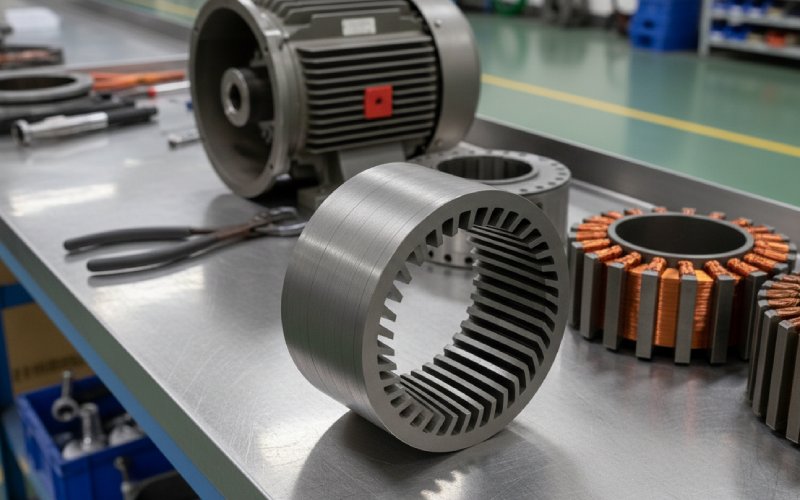
The production penalties are familiar. Skew complicates stacking control. Segment indexing matters more. Interlock strategy matters more. Runout tolerance gets less forgiving. In stator-skew variants, winding space and conductor length can suffer; one older but still useful source notes reduced effective slot area and higher conductor length, which translates into higher resistance. On the rotor side, shaped parts and segmented builds add process steps and inspection burden. None of that makes skew a bad choice. It just means the lamination stack has to earn its angle.
We do not start with “more skew equals less noise.” That shortcut burns time.
We start with the disturbance map. Which harmonic orders dominate torque ripple. Which force orders are close to structural modes. Which operating points matter commercially. Then we choose the smallest skew that breaks the bad alignment without taking too much from the working field. Often that lands near one slot pitch. Sometimes it does not. In some machines, 1.3 to 1.5 slot distance can hit a better compromise for selected harmonic weakening while leaving the fundamental close to 0.99. In others, that much angle is already too expensive in torque, start performance, or manufacturability.
A practical screening flow for rotor lamination stacks is simple enough:
That last point is less glamorous. It is also where many good simulations go soft.
Because they solve a very specific problem well.
Not every motor needs skew. Some topologies can reach the target with slot-pole selection, tooth shaping, notching, magnet shaping, or control-side compensation. But when the brief is smoother torque, quieter running, and a lamination-stack change that stays inside the electromagnetic core rather than pushing work onto software, skew remains one of the cleanest tools available. Recent papers keep refining the method. The underlying reason has not changed: phase-shift the axial slices, stop the disturbances from stacking, keep as much useful field as possible.
That is the engineering value of skewed rotor laminations. Small angle. Large consequence.
There is no universal number. Around one stator slot pitch is a common starting point because it can suppress slot-related torque ripple strongly while leaving the fundamental component nearly unchanged in some designs. But load point, saturation, slot-pole combination, and noise target can shift the optimum.
Not always in a meaningful way, but larger skew angles do tend to reduce the torque-producing field component. One reported result showed less than 2% average torque loss at one slot pitch in a reluctance machine, while larger skews caused much bigger penalties. Machine family matters.
Because the force distribution changes. Skew spreads slotting-related force peaks along the axial length, weakening the force-wave patterns that excite the stator and housing most strongly. Lower ripple helps too, but the force-wave redistribution is the deeper reason.
Continuous skew is the limiting case. Step-skew is often the production answer because it captures much of the same averaging effect with segmented lamination stacks that are easier to build and inspect. The caution is that segment transitions can create axial field effects, so final NVH and bearing checks still need proper 3D analysis.
Sometimes. Often not. Skew is strong against slotting-related disturbances, but it is only one lever. If the dominant issue comes from saturation behavior, back-EMF harmonics, radial-force coincidence, or structural resonance, the lamination stack may need skew plus geometry tuning, not skew by itself.
Process repeatability. The electromagnetic design can be right and the product can still drift if segment indexing, bonding or interlock consistency, stack compression, and axial alignment are not held tightly in production. The skew angle on paper is only half the part.