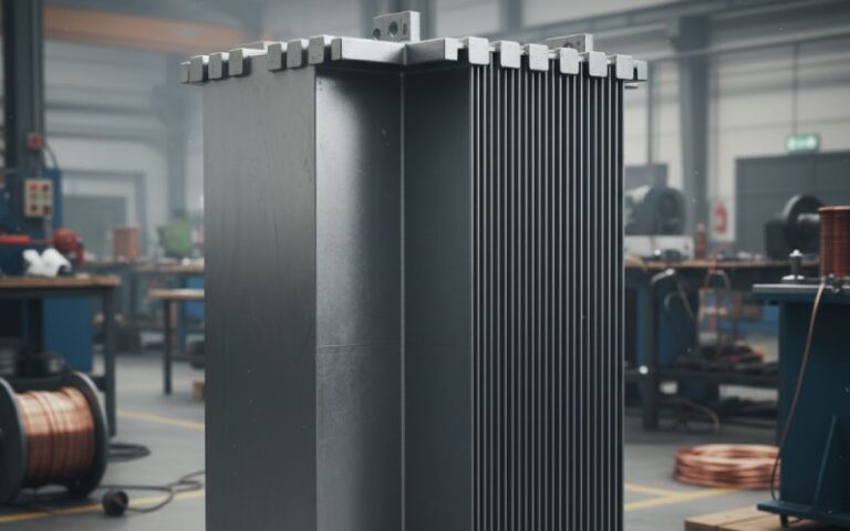
Let Sino's Lamination Stacks Empower Your Project!
To speed up your project, you can label Lamination Stacks with details such as tolerance, material, surface finish, whether or not oxidized insulation is required, quantity, and more.
Most laminated PM rotors end up with one of three realities: a metallic sleeve that limits speed and losses, a composite sleeve that limits temperature and cooling, or a banding process that quietly limits production yield. The trick is not “finding the best” option. It is accepting which constraint you are willing to live with for the next product generation.
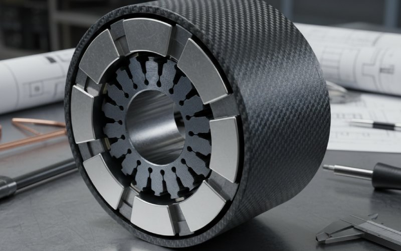
Once you move from solid rotors to laminated stacks, the sleeve is no longer clamping a simple cylinder. It is trying to keep together a stack of thin plates, magnets, adhesives, and sometimes pole sleeves or wedges. The stress field stops being clean. Radial compliance of the lamination stack, slotting, keyways, and duct features shift the hoop stress path and change how the band or sleeve shares load with the magnets.
Analytical models that treat the magnet and sleeve as two perfect concentric rings start to miss important interactions as soon as the lamination stack becomes tall, slotted, or skewed. That is exactly why more recent work explicitly couples the sleeve shrink fit, magnet elasticity, and rotor geometry in both radial and axial directions, instead of solving each piece in isolation.
So when we talk about “sleeve and banding options” for laminated PM rotors, we are actually talking about how you choose to route mechanical stress around a stack that was optimized for electromagnetic performance first and for structural behaviour only later.
Engineers typically fall into three families of containment for laminated PM rotors: metallic sleeves, composite sleeves (usually carbon-based), and banding-only approaches using fiber or tape wound directly around the lamination stack or outer magnets. Commercial machine builders and academic work both keep circling around these families because the core trade-offs refuse to disappear.
Metal sleeves give you decent temperature capability and good thermal conduction, but they introduce rotor eddy-current losses and add mass at the largest radius. Composite sleeves cut losses and inertia but struggle with heat and curing constraints. Pure banding, often done with automatic machines, leans more on process control and pre-tension than on material bulk.
The lamination stack sits under all of this, slightly elastic, slightly discontinuous, and that detail usually decides which of the three paths actually works in production.
For laminated PM rotors, metallic sleeves are often the default starting point. Inconel 718, stainless steels, and titanium alloys show up over and over because they combine yield strength in the hundreds of MPa range with acceptable toughness and manufacturability.
With a lamination stack under the sleeve, you care about three things more than usual.
First, the sleeve does not see a perfectly rigid core. The laminations compress under shrink fit and centrifugal loading, which reduces contact pressure at speed compared to what simple thick-cylinder equations predict. Modern analyses explicitly include lamination modulus and slot geometry when computing the interference fit and allowable speed, because the effective radial stiffness can be significantly lower than solid steel.
Second, the lamination stack may not give you a smooth outer surface. Skew, step-skew, or vent-channel stampings create a wavy OD. If you simply grind it round and slide on a tight metallic sleeve, you risk local over-stress at the remaining ridges or, worse, incomplete contact that compromises heat flow from magnets into the stack and then into the shaft. Several industrial designs intentionally keep a modest sleeve thickness and rely on carefully specified grinding and runout limits so the sleeve can settle without unpredictable local yielding.
Third, the sleeve becomes an active part of your loss budget. A continuous conductive tube around a laminated rotor forms a low-resistance path for high-frequency fields leaking from magnets and slots. That translates into rotor eddy-current loss and heat right where your magnets least want it. More recent work explores laminated metal sleeves, such as axially segmented titanium sleeves with insulating layers, which cut eddy-current density while keeping most of the mechanical benefit.
The net result: metallic sleeves are attractive on laminated rotors when you either need high temperatures, relatively modest surface speed, or a reliable thermal path. They are unhelpful if your design is already loss limited and spinning at the high end of what the magnets can mechanically survive.
Carbon-fiber sleeves around laminated PM rotors became popular because they almost remove rotor eddy-current loss from the containment structure and allow higher surface speed before stress limits are reached. Typical values quoted in industry surveys show maximum surface linear speed around 240 m/s for metal sleeves and roughly 320 m/s for fiber sleeves, with suitable layup and pre-tension.
The challenge is that composite sleeves behave very differently when wrapped on a lamination stack.
Fiber sleeves are excellent in the hoop direction but less stiff radially. Under high-speed operation, they hold magnets in compression, but their low thermal conductivity means that heat generated in magnets or end regions has trouble escaping. Several studies point out that simply increasing composite sleeve thickness to gain stress margin backfires: the thicker sleeve pushes the air gap out and drops flux density while also making cooling worse and raising magnet temperature.
Manufacturing route matters more than many specification sheets imply. Direct-wound carbon sleeves on a rotor can reach radial pre-stress on the order of a few hundred MPa, limited partly by magnet temperature tolerance during curing and the capability of your winding process. Pressed-on carbon sleeves, manufactured separately and then expanded and fitted onto the rotor, can achieve higher net compressive stress at operating conditions but require very accurate control of dimensions and interference.
When the core is a laminated stack with surface magnets, these differences become practical issues.
A direct-wound sleeve must follow every geometric imperfection of the stack, and the resin flow can be disturbed by lamination vent holes or slot openings. A pressed-on sleeve needs a smooth, precisely machined OD on the stack and magnets; otherwise, you get local gaps that erode both stress margin and stiffness. On small, extremely high-speed rotors, research results show that the sleeve thickness and interference fit are tightly coupled; there is often a very narrow region where magnet tensile stress, sleeve stress, and manufacturability all remain acceptable.
Newer composite approaches add yet another twist: automated fiber placement using thermoplastic tapes allows tightly controlled hoop tension and higher modulus fibers, while also reducing water uptake and dimensional swell of the sleeve. For laminated rotors operating in hot, wet environments, these details can be the difference between stable clearance and rubs after a few thousand hours.
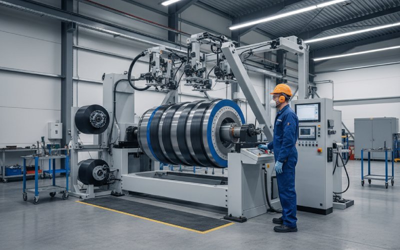
When people say “banding” they sometimes mean the material (a fiber bandage), and sometimes the process (automatic winding of pre-impregnated tape with defined pre-tension). For laminated PM rotors, the process is what really changes the game.
Dedicated banding machines for permanent magnet rotors control tape tension, rotation speed, and curing in a compact station. This is attractive when you have lamination stacks with magnets on the OD or slightly buried in slots, because the banding operation can adapt to different rotor geometries without changing a machined sleeve.
However, the lamination stack pushes back. Literally.
Each lamination layer is insulated, so the effective radial stiffness is lower than a solid ring. Under band tension, the outer laminations can collapse slightly, changing the final pre-stress once the rotor is at speed and temperature. Better banding processes try to account for this by combining measured rotor compliance, temperature compensation, and sometimes staged winding with different tensions. Recent research on rotor sleeve winding techniques suggests treating the winding and curing as part of the structural design, not just as a final assembly step.
Banding also interacts strongly with axial retention features: end caps, shoulders, and lips. These features interrupt the lamination stack and create local stress concentrations under hoop tension. For example, a chamfer at the transition between the lamination OD and an end ring can relieve stress in a metal sleeve but may create resin-rich pockets in a composite band, which then crack under repeated thermal cycling. Here the lamination stack geometry decides how far you can push band tension before long-term reliability drops off.
Recently, hybrid and laminated sleeves have started to show up in the literature and in early products. The idea is simple: instead of choosing between “conductive and strong” or “insulating and less conductive”, you combine them in a structured way.
One branch explores laminated metallic sleeves, such as titanium alloy sleeves with axial segmentation and insulation between segments. Simulations and tests show that these sleeves can cut rotor eddy-current losses significantly compared with solid titanium sleeves, while maintaining most of the mechanical capability. For a 10 kW, 30,000 rpm high-speed PMSM, a laminated titanium sleeve with an insulating layer reduced rotor eddy current losses compared with both solid titanium and composite sleeves, while staying within allowable stress limits.
Another branch explores composite sleeves with embedded conductive paths, for example sleeves that embed copper features into an otherwise composite structure. Recent work reports that such copper-embedded composite sleeves can improve stress margin at high speed compared with a pure composite sleeve, thanks to tailored stiffness and pre-stress patterns.
For laminated PM rotors, these hybrid sleeves offer something useful: they let you separately tune electromagnetic loss and mechanical performance while still conforming to a lamination stack that might not be completely ideal from a structural perspective. They do require more complex manufacturing and careful analysis of thermal behaviour at the interfaces, though.
The table below contrasts typical options as they apply to laminated PM rotors with surface or near-surface magnets. Values are indicative, not universal; they reflect trends reported across several industrial and academic sources.
| Option on laminated PM rotor | Typical materials and structure | Approximate surface speed range (m/s) | Temperature capability (rotor region) | Rotor loss impact | Thermal path from magnets | Process considerations with lamination stack | Typical use case pattern |
|---|---|---|---|---|---|---|---|
| Solid metallic sleeve shrink-fitted on lamination stack | Inconel 718, stainless steel, titanium; single-piece tube | Up to about 200–240 with careful design | Up to roughly 250–290°C before material and magnets limit system | Higher rotor eddy-current loss due to conductive tube | Good conduction from magnets to laminations and shaft | Requires smooth, accurate lamination OD; sensitive to stack compliance and slots; shrink-fit must consider lamination modulus | Medium and high-speed machines with tough environments where thermal robustness matters more than peak efficiency |
| Composite sleeve (filament wound or pressed-on) | Carbon fiber or hybrid fiber, epoxy or thermoplastic matrix | Around 250–320 when layout and pre-stress are optimized | Often limited to about 150–180°C by matrix and magnet grade | Very low eddy-current loss in sleeve; losses mainly in magnets and laminations | Poor radial conduction; sleeve can act as thermal barrier | Direct-wound sleeves adapt to geometry but depend on curing profile; pressed-on sleeves need accurate OD and control of interference on compliant stack | High-speed machines where efficiency and low rotor loss are dominant, and cooling is handled elsewhere |
| Automatic fiber banding over lamination stack | Prepreg tape or dry fiber with resin, wound in multiple passes | Similar to composite sleeve if thickness comparable; often around 250–300 | Matrix-limited; typically similar to composite sleeves | Low sleeve loss; band thickness and material drive behaviour | Similar to composite sleeves, sometimes worse if resin-rich | Process-sensitive: lamination compliance, vent holes, and end-step geometry affect final tension; good for flexible rotor families | High-speed rotors produced in variety, where changing a machined sleeve per variant would be too costly |
| Laminated metallic sleeve | Segmented titanium or steel sleeve with insulation between segments | Comparable to metallic sleeves, sometimes slightly lower | Similar to base alloy; local temperature may be better due to lower loss | Reduced eddy-current loss compared with solid sleeves while remaining conductive | Better than composite, somewhat lower than solid metal due to segmentation and insulation | More complex machining and assembly; stack OD must still be precise; interface insulation needs durable bonding | Machines where rotor loss is limiting but composite sleeves are not acceptable for temperature or structural reasons |
| Hybrid composite sleeve with embedded conductors | Composite matrix with embedded copper or other conductors | Designed for high-speed; ranges similar to composite sleeves | Matrix-limited, often in same range as high-end composites | Can tune loss by adjusting conductive volume and pattern | Conduction similar to composite with localized improvements | Requires advanced manufacturing (AFP or tailored layup); alignment with lamination features important | Early-stage designs targeting aerospace and other multi-constraint machines that need both low loss and tailored stiffness |
These ranges sit on top of the lamination stack’s own limits: magnet tensile strength, lamination yield strength at temperature, and any stress raisers at keyways, vent slots, or shrink seats.
Lamination stacks are designed first for electromagnetic performance. That means slot opening, tooth width, bridge thickness, and rotor OD are all chosen to deliver a specific torque ripple, efficiency, and inductance profile. Structural consequences come later.
In high-speed PM rotors, this order of decisions sometimes leads to stacks with outer bridges that are thinner than ideal, or with web regions that are too flexible. Under sleeve or band pre-stress, these features deform, pushing magnets slightly and changing the local air gap. Under operating speed, they flex outward again. Any sleeve or band choice that ignores this will behave differently on the real rotor than in the calculation.
Modern design flow for laminated PM rotors therefore tends to do the following, even if not always documented that clearly.
First, it builds a mechanical model of the lamination stack and magnets alone. Shrink fits, bands, and sleeves are added only after the lamination compliance is understood. This step reveals whether bridges and webs will distort before they even reach their nominal stress limits.
Next, the sleeve or band design is tuned to that compliance. For a very stiff lamination stack, a thinner composite sleeve with high pre-stress may be optimal. For a softer stack, a metallic sleeve with lower interference but more thickness can provide the same containment with less sensitivity to geometric imperfections.
Finally, rotor eddy-current and thermal models are updated with the actual sleeve or band geometry. Studies show that sleeve material and structure can move loss from the magnets to the sleeve or away from both, but the right answer depends on speed, frequency content, and cooling system more than material choice alone.
The lamination stack geometry pushes these steps in one direction or another; sometimes subtly, sometimes very strongly.
It helps to think in a few stylised cases rather than in universal rules, because lamination stack and application details dominate.
Consider a small, ultra-high-speed rotor in the tens to hundreds of watts, running at several hundred thousand rpm with a laminated stack. Here, the magnets are tiny, and the lamination OD is small. Composite sleeves or direct banding make sense: eddy-current losses in such a small metal sleeve could represent a large fraction of total loss, and the thermal path through the shaft and bearings is often enough. The lamination stack is usually simple and can be ground to a very precise OD, helping the composite sleeve behave predictably.
For a high-speed industrial compressor drive in the hundreds of kilowatts to megawatt range, running at tens of thousands of rpm with a laminated stack, the picture changes. Rotor diameter is larger, the environment hotter, and fault conditions harsher. Metal sleeves become more attractive because of their temperature capability and toughness. If rotor loss is problematic, laminated metallic sleeves or carefully designed venting and shielding can reduce it, while composite sleeves might struggle with heat rejection and long-term stability at elevated temperatures.
In automotive traction motors using laminated rotors with surface magnets or buried magnets close to the OD, composite sleeves and banding are attractive, especially with carbon-fiber-reinforced sleeves. They reduce rotor inertia and can help with range and transient response. Yet they demand well-controlled curing and robust management of magnet temperature, and their thermal barrier effect must be balanced by aggressive cooling elsewhere in the system.
Each of these cases is driven by the lamination stack geometry and by the broader system, not by an abstract preference for one material family.
If you already know your electromagnetic design and lamination stack, the sleeve or band decision collapses into a few practical questions.
You ask how much mechanical speed margin you require, including overspeed tests and fault cases. You ask how much rotor eddy-current loss you can accept before magnets exceed their temperature budget. You ask what manufacturing variation is realistic for stack OD, runout, and straightness. You ask in what conditions the machine has to start, stop, and soak.
Once those boundaries are clear, the comparisons from earlier stop being generic.
If your lamination stack is stiff, your rotor loss budget is tight, and you can keep rotor temperatures in check, a composite sleeve or banding solution probably ends up ahead, especially when automated winding or automated fiber placement is available.
If the environment is hot, contaminants are likely, and your lamination stack has tricky geometry or large diameter, a metallic or laminated metallic sleeve is often the safer option, possibly with local features to control loss and manage stress around vent holes and keyways.
If your product family includes several rotor variants that share lamination stacks but differ in magnet grade, pole count, or speed, then banding as a process becomes attractive: one lamination tool, one basic rotor family, several different banding patterns and thicknesses. The banding station becomes part of your product roadmap, not just a work cell.
In all of these directions, the lamination stack is not a passive participant. It sets stiffness, tolerances, and geometry. The sleeve or band then works with that reality, or it fights it. The best designs work with it, by choice.