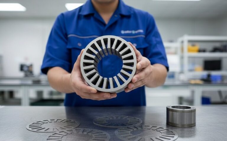
Let Sino's Lamination Stacks Empower Your Project!
To speed up your project, you can label Lamination Stacks with details such as tolerance, material, surface finish, whether or not oxidized insulation is required, quantity, and more.
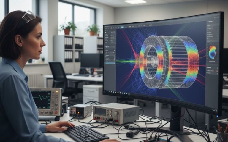
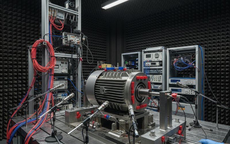
If you strip away the control tricks and the marketing, most of the acoustic trouble in an SRM comes down to a simple fact: the lamination stack behaves like a thin ringing shell, and the tooth shape decides which force harmonics hit that shell the hardest. Treat those two pieces as one coupled design problem and you can usually buy several decibels of noise reduction without giving away much torque or efficiency.
Old vibration studies on four-phase SRMs already showed that the dominant airborne noise is driven by deformation of the stator lamination stack, not by the rotor or the housing by themselves. The tooth surfaces see strong radial electromagnetic forces; those forces excite ring and local tooth modes of the stacked laminations, and the steel turns into a very efficient acoustic radiator.
More recent multiphysics work connects this to the space–time spectrum of radial forces. The tooth forces can be decomposed into spatial orders around the air gap and temporal orders tied to switching frequency and mechanical speed. When a temporal order of the radial force coincides with a structural mode that has the same spatial pattern on the stator, vibration spikes. In SRMs this often happens for force harmonics of order (3N_0 \pm 1) around the circumference, which show up as clear noise peaks that hardly move with speed.
So while everyone talks about “SRM noise” in general, the job at lamination and tooth level is more precise. You are trying to reshape the radial force distribution so that the strongest harmonics either shift away from sensitive structural modes or smear out enough that they no longer drive any one mode efficiently.
Designers usually lock down yoke thickness, stack length, and frame fit early, for saturation and thermal reasons, and then live with whatever acoustic behaviour falls out. That is convenient, but it hides a lot of leverage.
Work on stator vibration has shown that yoke thickness and stack length move the main circumferential modes by hundreds of hertz. Thicker yokes lift natural frequencies and can push the worst modes above the main electromagnetic excitation band, especially in high-speed machines. At the same time, the way laminations are clamped or bonded to the frame controls damping and boundary conditions. A rigid shrink-fit shell with end plates gives very different mode shapes from a loosely clamped stack held by tie rods.
For tooth-shape work this matters because you are not designing against abstract frequencies. You are designing against the actual mode map of that specific stacked assembly. Change the stack building method and your beautifully tuned tooth tips may suddenly push energy into a different mode set. That is why any “tooth geometry optimization” that ignores the assembled stator modal model tends to disappoint once you build hardware.
Once the stack structure is understood, tooth shape becomes a way to re-weight the radial force spectrum instead of just a flux-density knob.
Analytical and numerical studies on SRMs show that radial force density on each tooth is roughly proportional to the square of the local air-gap flux density. The flux density itself is extremely sensitive to tooth-tip shape and local saturation. That means small geometric changes at the tip and at the tooth root can produce surprisingly large changes in the spatial distribution of radial force, without dramatic impact on average torque.
A few patterns show up consistently in the literature and in practical tuning:
Smooth, rounded tooth tips with carefully chosen pole arcs tend to soften the gradient of inductance near aligned position. That reduces sharp peaks in radial force when current is still high. Curved rotor poles paired with matching stator tooth tips have been shown experimentally to cut radial forces and acoustic noise while losing less than about half a percentage point in efficiency in some 8/6 machines.
Tooth-tip chamfers or small notches near the edges alter the local permeance at partial overlap. When done with a clear harmonic target in mind, these features can reduce specific spatial orders in the radial force, at the cost of some extra flux crowding elsewhere. Papers that combine such tooth shaping with tuned commutation angles report noticeable noise reductions without extreme penalty in torque ripple.
Varying tooth width or introducing multi-tooth patterns around the stator breaks the perfect periodicity of the force field. A recent study on multi-tooth stator–rotor modifications highlights combinations of trapezoidal teeth, pole bridges, and tip shaping that lower noise while keeping electromagnetic performance acceptable for automotive-scale drives. You can think of these patterns as controlled “defects” that intentionally spread radial force over several spatial orders instead of one dominant one.
None of these tricks works in isolation. Shift the tooth tip and the current waveform that used to be optimal is no longer quite right, because the inductance profile versus angle has moved. This is why “final” tooth geometries almost always emerge from a loop involving both field calculations and simple NVH metrics rather than a single static optimization.
Rotor geometry often gets optimized for torque density and windage first. Noise comes along for the ride. In SRMs with very high speed ranges, especially traction machines that run beyond 10,000 rpm, windage loss in the wide rotor slots is not trivial. A 2025 study on traction SRMs for three-wheelers showed that shrinking slot area with modified rotor slot shapes could cut windage loss while also improving acoustic behaviour, once the resulting radial force changes were captured in a full noise simulation and validated experimentally.
Other work on 8/6 SRMs has tested rotor pole-tip curvature and multi-segment pole profiles. By smoothing the effective pole arc and avoiding harsh saturation at the tooth sides, those designs reduced radial force peaks and the associated sound power with negligible impact on efficiency and torque capability.
From a lamination-stack point of view, the rotor is really a programmable source of spatial excitation. If you adjust rotor tooth shape without checking which spatial orders you are reinforcing, you may clean up one whine and create another, just at a different frequency. The better way is to extract the radial force spectrum at the stator teeth for each candidate rotor shape, line it up against the stator mode map, and reject any shape that increases force content near sensitive modes, even if its torque ripple looks slightly better.
Skewing is often introduced as a generic cure for torque ripple and acoustic noise, but the details of how lamination stacks are skewed matter a lot.
In practice, skew in SRMs is usually built by rotating successive laminations by a small angle, so that the stack forms an axial helix. This can be done on the stator, on the rotor, or on both. Experiments with single-phase and three-phase SRMs show that combining stator and rotor skew can significantly reduce vibration and acoustic noise, at the price of some drop in average torque and an increase in axial flux leakage. Reviews of skewed laminations report noise reductions on the order of a few decibels for multi-layer skewed configurations, which is already noticeable inside a vehicle cabin.
For lamination stack design this means skew is not just a switch; it is a phase offset between the radial force fields along the axial direction. The effective excitation that reaches a given stator mode is the axial sum of these phased contributions. If your dominant mode has a fairly uniform axial shape, then a skew pitch close to one stator pole pitch will cause destructive interference in the key spatial harmonic and help. If you have modes with strong axial variation, a simple uniform skew may not do much, and you are better off with stepped skew or mixed patterns where sections of the stack are skewed differently.
There is also the mechanical side. Skewing laminations changes how teeth share load through the stack and may slightly modify the mode shapes themselves, especially in short axial length machines. It also complicates manufacturing, stacking, and alignment of slots for windings or cooling channels. So the gains have to be measured against these practical headaches, not just against a clean FEA model.
The table below summarizes several widely used lamination and tooth-geometry tactics and their typical influence on forces, noise, and torque, based on trends reported in recent SRM research and industrial practice.
| Design tactic | Main effect on radial force spectrum at teeth | Typical change in A-weighted noise (order of magnitude) | Typical impact on torque ripple | Notes for lamination stack design |
|---|---|---|---|---|
| Rounded tooth tips and optimized pole arc (stator and/or rotor) | Reduces sharp peaks near aligned position, shifts energy toward lower orders, smooths force versus angle | Reduction of a few decibels at dominant whine frequencies when paired with suitable current shaping | Small reduction in torque ripple if current profile is retuned; sometimes a slight drop in peak torque | Works best when modal analysis shows dominant modes near high-order harmonics that can be softened by smoother flux distribution |
| Tooth-tip chamfers or edge notches | Attenuates specific spatial harmonics linked to edge saturation, redistributes force toward the tooth center | Often 1–3 dB lower noise around targeted harmonics, but can introduce new minor peaks elsewhere | May increase torque ripple slightly if commutation is not adjusted; average torque usually nearly unchanged | Needs close link between harmonic analysis and geometry; over-aggressive notching can raise local losses and stress |
| Multi-tooth or trapezoidal stator/rotor patterns | Breaks periodicity; spreads force over multiple spatial orders with lower individual amplitudes | Can lower narrowband tonal noise significantly, sometimes at the cost of broader-band noise that is less objectionable | Torque ripple usually improves if patterns are chosen carefully; wrong combinations can worsen it | Assembly tolerances become more critical; lamination punching and stacking must keep tooth positions consistent |
| Rotor slot area reduction with reshaped slots | Lowers windage-induced pressure fluctuations and slightly alters radial force distribution | Noise cuts come both from reduced aerodynamic noise and softer electromagnetic excitation; a few decibels are realistic at high speed | Torque maintained if average air-gap permeance is preserved; extreme slot shrinkage can hurt torque | Influences mechanical stress in rotor laminations; modal analysis should include rotor if speeds are very high |
| Stator and/or rotor skew over one pole pitch (uniform) | Smears spatial harmonics along axis; reduces coherent excitation of modes with uniform axial shape | Several decibels of reduction for strong tonal components when skew is tuned to dominant harmonic | Average torque drops and copper losses may rise; torque ripple usually decreases | Requires careful lamination stacking jigs; affects end-winding geometry and cooling paths |
| Thicker yoke and increased stack stiffness | Moves circumferential modes up in frequency; can separate them from main force harmonics | When successful, moves main resonances out of operating band so tonal noise drops sharply | Minimal direct change to torque ripple; may slightly affect magnetizing current | Added steel mass and cost; must be checked against saturation and size constraints |
The numbers are intentionally vague, because the exact gains depend heavily on machine size, pole/slot combination, and how sharply your force and structural spectra cross. The useful thing is the direction: which design knobs tend to push which parts of the coupled system.
Many published models treat the stator lamination stack as perfectly glued or perfectly clamped to the frame. In reality, you might have partial contact, small gaps, or regions where varnish and interlock tabs dominate the stiffness. Experimental mechanical studies on SRM stators show that real boundary conditions can shift natural frequencies by tens of percent compared with ideal supports.
For noise mitigation, this means a few practical things. The uniformity of lamination stacking affects axial mode shapes. If each packet of laminations is slightly misaligned, you unintentionally introduce local skew and stiffness variations that can either help or hurt. Random skew tends to add damping but can also excite asymmetrical modes that were not present in the model.
Clamping force matters as well. High clamping compresses the stack, increases friction between laminations, and can add damping, but it may also shift modes upward. Potting or resin between stack and frame can provide strong damping at some frequencies while creating new coupled modes with the housing at others. It is rarely all good or all bad, and you only see the trade-off once you assemble and test.
So when you tune tooth shapes in FEA, it is worth stepping back and checking whether your assumed boundary conditions match the assembly process the factory actually uses. Sometimes a small change in how the stack is pressed into the frame buys more noise reduction than another round of tooth-tip refinement.
Most teams already have a 2D or 3D electromagnetic model of the SRM and probably a separate structural model of the stator and housing. The missing piece is usually the tight coupling between them at the tooth surface. A practical loop might look something like this, without trying to be mathematically perfect.
First, fix an initial lamination stack design: yoke thickness, stack length, frame fit, clamping concept. Run a structural modal analysis on the assembled stator–housing–winding model and note the main modes with significant radial tooth motion in the key frequency band for your application. The goal is to identify a small set of “sensitive” modes instead of staring at dozens of eigenvalues.
Then, use your electromagnetic model to compute radial force distributions on each tooth over one or two electrical cycles at several operating points. Project those forces onto the spatial mode shapes you care about. This tells you which parts of the radial force spectrum actually pump energy into real modes, not just what harmonics exist in theory.
With that mapping in hand, start adjusting tooth and rotor geometries. Rounded tips, chamfers, modified pole arcs, and multi-tooth patterns all become ways to reduce the projection of the radial forces onto the sensitive mode shapes, even if the total force magnitude barely changes. Skew and yoke changes sit in the same loop: they alter the structural side rather than the electromagnetic side.
What helps in practice is not obsessive optimization of one design variable but watching how each change moves three numbers together: dominant force harmonics, dominant structural modes, and simple acoustic metrics like sound power or overall A-weighted level in a narrow band around the annoying whine. Back-to-back prototypes, even at reduced scale, give much better insight than trying to push every decision through a single multi-objective optimizer.
If you are working on an SRM and the datasheet noise numbers are uncomfortable, it is tempting to throw more attention at current waveforms and converter strategies. Those tools are still useful. But the work over the last few decades makes something else clear: once you see the lamination stack as an elastic shell driven by tooth-level radial forces, tooth geometry and stack design stop being “detail drawings” and become a primary NVH control surface. Getting those pieces right shrinks the list of acoustic problems you need to fix in software and gives your control team a much easier machine to live with.