Let Sino's Lamination Stacks Empower Your Project!
To speed up your project, you can label Lamination Stacks with details such as tolerance, material, surface finish, whether or not oxidized insulation is required, quantity, and more.
Electric machines can feel mysterious until you meet the two leads of the story: the stator, standing still, and the rotor, racing to follow. Think of them as dance partners—one sets the rhythm, the other locks in and moves. This article is your plain‑spoken but technically rigorous tour of how that dance creates torque across the major motor families—and how to design, select, cool, diagnose, and care for them so they run whisper‑quiet and last for years.
The stator is the stationary magnetic “stage” that carries windings or magnets. The rotor is the rotating “dancer” that develops torque by interacting with the stator’s field and delivers mechanical power through the shaft. In most AC machines, the stator creates a rotating magnetic field; the rotor chases it with a small speed gap (induction) or locks to it (synchronous).
All motors exploit two pillars: changing magnetic fields induce currents (Faraday), and currents in magnetic fields feel force (Lorentz). Arrange windings so the stator’s field rotates; arrange conductive paths in the rotor so induced or supplied currents interact with that field. The cross‑product of field and current produces a tangential force, summed around the air gap into torque.
Three‑phase stator windings create a rotating magnetic field whose no‑load mechanical speed is the synchronous speed Ns = 120·f/P (rpm), where f is line frequency (Hz) and P is the number of poles. This single relation sets the ceiling for AC machine speed.
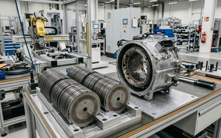
In a squirrel‑cage induction motor, the stator’s rotating field sweeps past rotor bars, inducing currents that create their own field; the interaction develops torque. The rotor must lag slightly—this difference from Ns is “slip,” and at rated load most industrial motors run with roughly 1–5% slip. Construction is rugged: a laminated iron stator with copper windings, and a laminated rotor with die‑cast or bar‑and‑ring conductors (aluminum or copper).
Here, the rotor carries its own steady magnetic field (DC wound field via slip rings, or permanent magnets). It doesn’t “chase” the stator’s wave—it locks to it. Because the rotor field is constant, the motor can run at unity or even leading power factor by trimming field current, which is prized in large industrial plants. Note: a synchronous motor isn’t self‑starting; damper windings or a VFD are used to accelerate it to near‑synchronous speed before pull‑in.
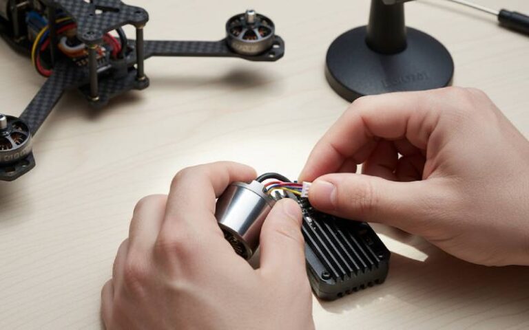
A stationary field from stator coils or permanent magnets spans the air gap; the rotor (armature) windings connect through a commutator that mechanically switches current to keep torque unidirectional. Elegant, high starting torque, wide speed control—at the cost of brush wear and maintenance.
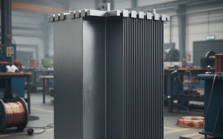
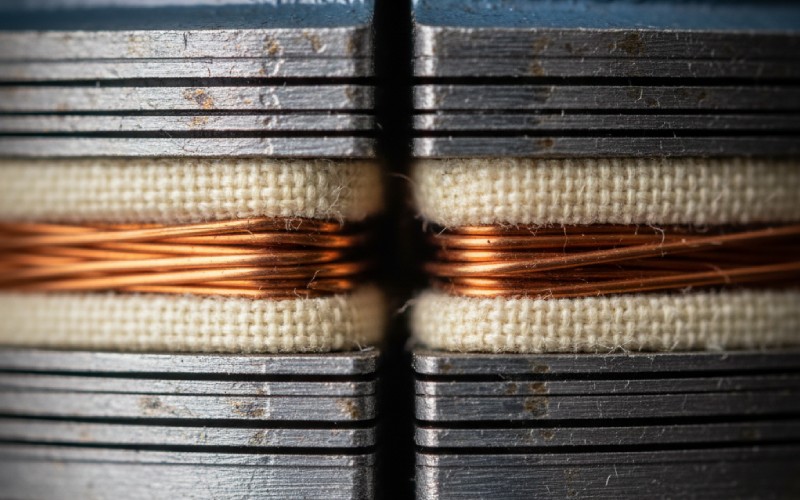
Both stator and rotor cores are stacks of insulated electrical‑steel laminations. Laminating breaks up eddy‑current loops in the iron and dramatically reduces heating and loss. Typical industrial laminations around 0.5 mm are common, with thinner grades such as 0.35 mm or 0.27 mm cutting iron losses further at higher electrical frequencies.
Designers skew cage bars a fraction of a slot pitch so a given rotor bar is never perfectly aligned with a single stator slot. The payoff: lower cogging, smoother torque, and reduced acoustic noise—especially at low speed. It’s a classic, low‑cost way to smooth torque without electronics.
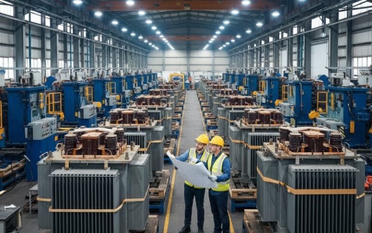
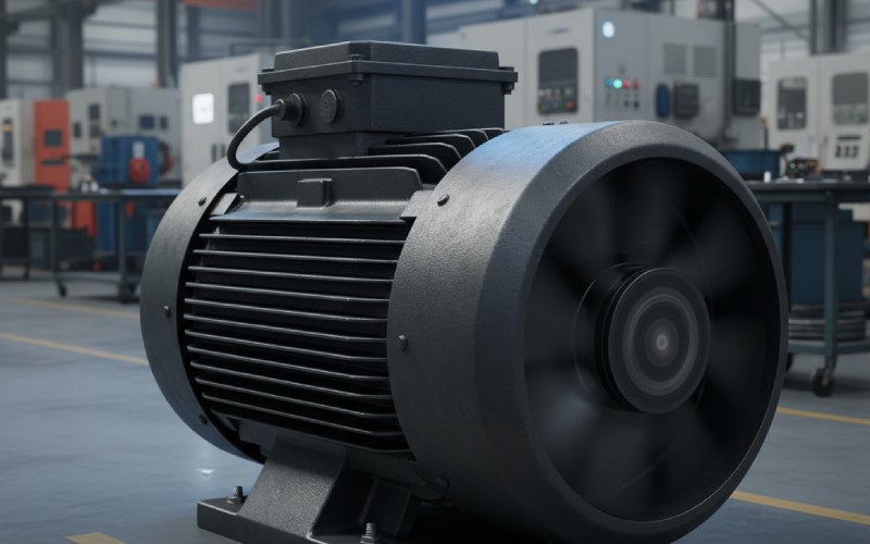
Most general‑purpose industrial motors are totally enclosed fan‑cooled (TEFC): outside air never flows through the windings; a shaft‑mounted fan blows across the finned frame to shed heat. For harsher duty, you’ll see air‑to‑air or water‑to‑air heat exchangers, plus insulation systems rated Class F or H to handle temperature rise.
Upgrading a cage from aluminum to die‑cast copper increases rotor conductivity, cutting I²R loss and raising efficiency; lab and field trials report ~15–23% lower motor losses and 1.2–1.7 percentage‑point efficiency gains, design‑dependent. In some designs, that allows a smaller frame at equal performance. 6
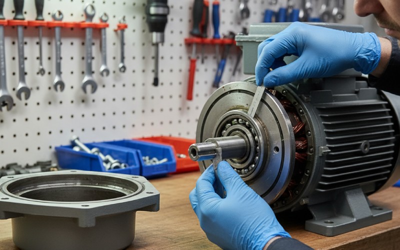
Across fleets, roughly half of motor failures trace back to bearings—commonly lubrication, contamination, misalignment, or stray shaft currents with VFDs. Mitigation spans proper grease practices, shaft‑grounding, insulated bearings, and clean alignment. Condition monitoring (vibration, temperature, and Motor Current Signature Analysis) catches issues early.
| Machine type | Stator field source | Rotor field/current source | Start behavior | Speed vs. Ns | Typical wins |
|---|---|---|---|---|---|
| Induction (squirrel‑cage) | 3‑phase AC windings → rotating field | Induced in rotor bars (Al/Cu cage) | Self‑starting | Nr < Ns (slip 1–5% typical at load) | Rugged, low maintenance, cost‑effective |
| Synchronous (wound‑field) | 3‑phase AC windings → rotating field | DC field on rotor (slip rings/brushless exciter) | Needs damper/VFD to start | Nr = Ns | Constant speed, power‑factor control |
| PM Synchronous | 3‑phase AC windings + magnets on rotor | Permanent magnets | VFD for start/control | Nr = Ns | High efficiency, high power density |
| Brushed DC | PM or DC stator field | Armature coils via commutator | Self‑starting | Broad, voltage‑set | High starting torque, simple control |
Linear motors “unroll” the geometry: a flat “stator” on the vehicle and a track “rotor” (or vice‑versa). The same stator‑makes‑a‑wave, rotor‑rides‑the‑wave principle powers high‑acceleration transit without relying on wheel adhesion.
Once you internalize that the stator writes a moving magnetic script and the rotor learns to read it—either by induction or by carrying its own field—the rest is engineering levers: frequency, poles, slip, materials, cooling, and care. Use the speed formula to set expectations, skew and slotting to tame ripple, copper and thin steel to chase efficiency, TEFC and insulation to hold the temperature line, and condition monitoring to keep the bearings happy. That’s the stator‑and‑rotor story, told so you can put it to work on your next spec, retrofit, or root‑cause.