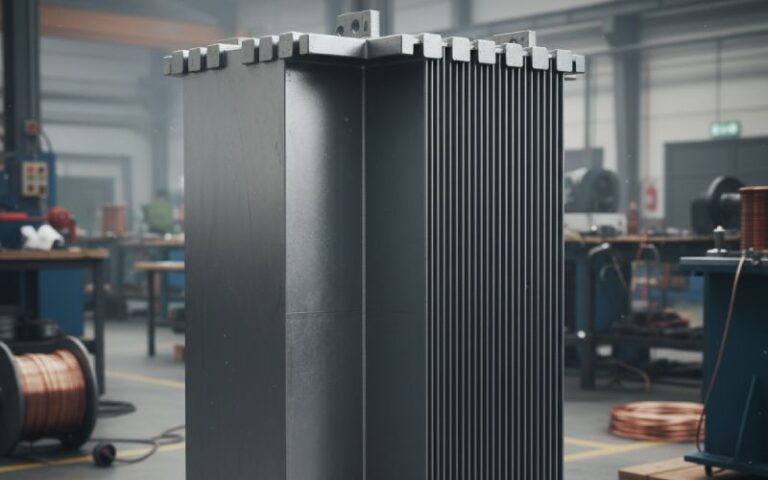
Let Sino's Lamination Stacks Empower Your Project!
To speed up your project, you can label Lamination Stacks with details such as tolerance, material, surface finish, whether or not oxidized insulation is required, quantity, and more.
Integrated drive units do not forgive geometry mistakes. Once you freeze the stator package and rotor proportions, you lock in torque density, acoustic behavior, cooling complexity, BOM, and even how service techs swear at the unit ten years later. Software trims the edges; the metal sets the shape of the problem.
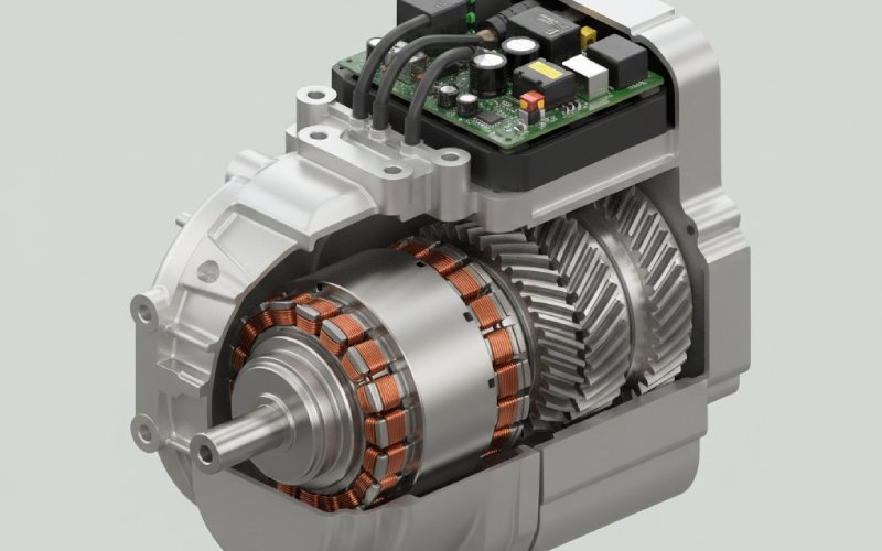
Most EDU papers talk about efficiency maps and power density, but vehicle teams care about a different set of numbers: axle-to-axle space, crash rails, subframe pick-up points, and battery tunnel clearance. Reviews of modern EDUs show the same trend: motor, gearbox, and inverter are sized together as one mechanical object, not as three separate components that just share a shaft.
That means stator OD and rotor envelope are not “motor design variables” in isolation. They are competing claims on volume with the gearset, differential, and inverter. High-speed e-axles from AVL and others show this clearly: they squeeze rotor length and diameter hard, then pay for it with higher speed and more reduction ratio in the gear train.
So any discussion of rotor size trade-offs that ignores the EDU casting, the half-shaft angles, or the inverter brick thickness is already incomplete.
In theory, you could start from torque and base speed, choose a motor topology, then let CAD figure out where to put everything else. In a real program, it often runs the other way. The body-in-white hardpoints give you a motor “bounding cylinder” between the half-shafts and the inverter face. The gearbox wants its own chunk of that space. Thermal engineers then claim wall thickness and oil galleries. Only after this tug-of-war do you discover what rotor diameter and stack length are actually left.
Lucid’s compact drive is a good example: rotor, stator, cooling hardware, and planetary set are tightly nested, with the differential pulled into the rotor shaft. The motor is not free to grow axially because the gearset must sit in line; it cannot grow radially because the housing still has to live between suspension members.
So the honest answer: neither stator nor rotor really comes first. The EDU envelope comes first, and the rotor/stator geometry is what you solve to make that envelope work electrically, thermally, and mechanically.
Everyone in this field knows the basic proportionalities. Torque scales with air-gap radius, axial length, and shear stress. It is tempting to chase torque by just pushing rotor diameter until the housing complains. That works for a while. Then the non-ideal stuff shows up.
Larger diameter drives rotor tip speed up for a given mechanical rpm. Centrifugal stress in the sleeve and magnets climbs with the square of speed, so mechanical safety margins shrink quickly once you go past a certain radius for a given maximum rpm. Studies of high-speed shafts and new rotor-cooling concepts underline how much effort is now going into managing these stresses and temperatures in compact EV machines.
On the other hand, long, slim rotors have their own issues. They increase bending modes, can amplify gear-mesh excitations in EDUs, and become annoying from a stack-up tolerance perspective. NVH papers on e-axles show how shaft and rotor modes couple with housing and gear dynamics in ways that are not friendly to cabin quietness, especially once you push motor speeds into the high teens of thousands of rpm.
All of that sits on top of the obvious: diameter affects copper path length in the stator, stator tooth flux density, and the amount of iron you need in the yoke. Length affects end-winding proportion, axial leakage paths, and sometimes cooling distribution. You already know the equations; what matters in an EDU is how these electromagnetic effects interact with the casting, the gears, and the oil.
Here is one way to summarize the geometry decisions you keep circling back to in integrated units:
| Rotor bias inside EDU | Typical D/L tendency | Helps with | Creates trouble with |
|---|---|---|---|
| Short, large-diameter | D relatively high, L short | Peak torque per axial mm, compact axial package, space for coaxial gearsets | Tip speed and sleeve stress, rotor cooling, magnet retention, eddy losses in PM machines, oil churning losses near the OD |
| Long, small-diameter | D modest, L long | Lower mechanical stress at high speed, easier containment, often nicer NVH for a given rpm band | Shaft dynamics, bearing span, packaging with planetary/differential, more end-winding proportion, housing length problems |
| Balanced | D and L both moderate | Robust efficiency over drive cycle, more flexible cooling layouts, easier integration with helical or parallel-axis gearboxes | Less “hero” numbers on single metrics like peak torque density, more negotiation needed across teams to keep the sweet spot |
The point is not that one row is “right.” It is that once you pick a bias, a whole family of secondary decisions become almost forced.
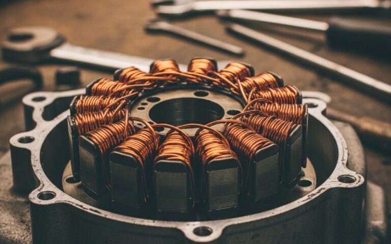
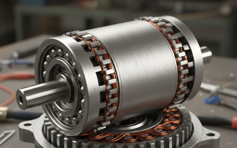
Modern EV machines use stator technologies that are already familiar: hairpin or bar-wound stators for high slot fill, segmented stator cores, concentrated windings in some designs. But when the motor lives inside an EDU, those choices stop being only electromagnetic.
Segmented stators with fractional-slot concentrated windings are attractive because they simplify manufacturing, allow high slot fill, and can integrate cooling channels into individual segments. Work from DOE and others shows such concepts meeting aggressive power-density targets with integrated cooling. However, segment joints, additional end-plate features, and complex coolant routing all eat space that could have belonged to rotor radius or gearbox elements.
Hairpin windings, as used in production motors like the Ampera-e, make good use of stator slot area and play nicely with automated manufacturing. In an EDU, though, the hairpin end turns want axial room. That pushes the motor axial length up or steals length from the gearset. It also produces dense copper regions right where cooling and busbar routing are already crowded.
The inverter packaging then feeds back: thicker power modules and busbars might drive a larger stator OD or force the motor to shift relative to the gearset, which can shift where you are allowed to place bearing shoulders and rotor supports. The geometry conversation loops.
EDUs are judged by customers through their ears more than through FFT plots. And rotor/stator geometry shows up strongly in those ears.
Rotor diameter and length change the stiffness and mass of the rotating assembly, and therefore the shaft’s bending and torsional modes. When this interacts with gear mesh frequencies and inverter switching harmonics, the result can be tonal noise that no software filter really erases. NVH-focused studies of e-axles emphasize early co-design between electromagnetic forces, structural modes, and gear dynamics, not late-stage patching.
Stator geometry also matters: narrow teeth and high slot counts shift force wave numbers and can push dominant excitation into less sensitive regions of the cabin’s acoustic transfer functions. But very high slot counts raise manufacturing complexity and may clash with the packaging rules for hairpins or segment joints. Again, trade-offs, not free wins.
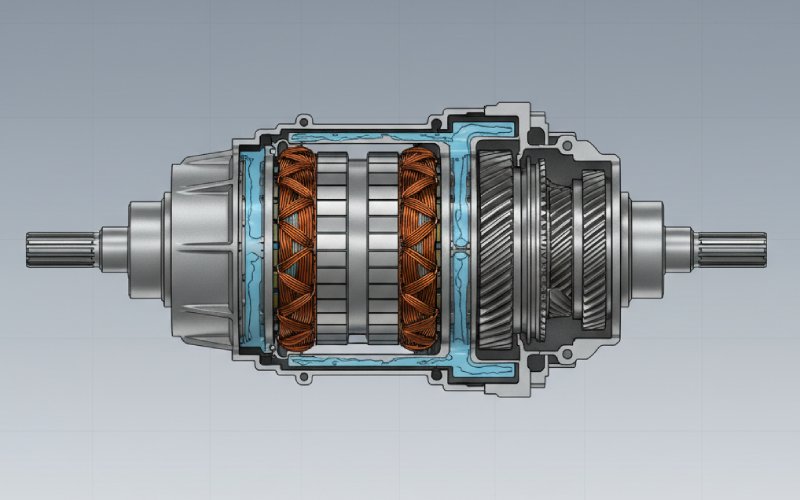
Look at current EDU cooling strategies and a pattern shows up. Oil or dielectric fluid often washes the rotor and stator, then hands heat off to a water–glycol loop and on to a radiator.The oil circuit shares space with gears, bearings, and seals, plus whatever the drivetrain team needs for lubrication and churning loss control.
Cooling reviews and selection guides now stress that you have to consider rotor, stator, housing, and even inverter as one thermal object. A fat rotor with high loss density may be fine electromagnetically but force you into complex ducted liquid cooling through the shaft or very aggressive oil jets, which increases pump power and design risk. A long, slim rotor spreads loss axially but might demand longer housings and more surface area for the same coolant flow, which is not free either.
The stator package interacts with this. Internal jackets, embedded channels in stator segments, and direct cooling of end windings all require cast-in features or inserts. Those features occupy radial and axial space that could have gone to rotor radius or gear face width.
Formal multi-domain optimization tools are useful, and recent work on integrated e-axle co-optimization with machine learning is impressive. But engineering teams still make first calls based on simple patterns.
One pattern: start from the vehicle and gearbox, not the motor. Lock the maximum allowable EDU outer envelope, gear reduction strategy, and inverter brick volume. That gives you a “budget cylinder” for the motor. Inside that budget, choose a rotor speed band that matches available magnet materials, containment tech, and customer NVH expectations.
Once the speed band is agreed, use rotor diameter as a shared currency among electromagnetics, mechanical, and thermal teams. Every extra millimeter of diameter should buy clear, quantifiable benefit in torque density or loss reduction, and its price should be visible in containment, tip speed, and oil churning. Axial length then becomes the variable that keeps efficiency along the drive cycle in a sensible place, rather than a silent creep at each design review.
A second pattern: treat stator packaging features as line items in the same budget. If segmented stators or complex cooling jackets are proposed, require explicit justification in terms of either manufacturing cost, repair strategy, or a measured improvement in efficiency or power density over a realistic drive cycle, not only at peak. Otherwise, that material is simply eating rotor real estate for unclear gain.
The trade space is not static. Reviews of recent traction motor developments show increasing attention to higher mechanical speeds, non-traditional rotor materials, and multi-rotor or axial-flux concepts to push power density without simply inflating diameter.
Carbon-fiber reinforced rotor sleeves and even structural rotor bodies are moving from research papers into serious prototypes, offering better containment at high tip speeds and opening the door to more aggressive rotor diameters in compact housings. Multi-stator multi-rotor architectures can stack torque-producing stages without increasing outer diameter, at the cost of mechanical complexity and sometimes axial growth.
On the stator side, new cooling layouts and integrated inverter-motor concepts mean the traditional “motor can with stuff bolted on” picture keeps eroding. Integrated designs that wrap the inverter around or inside the motor housing change which direction you can grow, and by how much, and they also shift where the heat actually goes.
So rotor size and stator packaging remain the two main levers for power density and EDU compactness, but the material and integration toolbox around them keeps expanding. That is good news, but it also means the old rules of thumb need regular checking against new data.
If you are responsible for an integrated drive unit, you are really deciding how much of your limited envelope belongs to rotor radius, how much to axial length, and how much to stator copper, steel, cooling structure, gearset, and inverter. Each millimeter has a job.
The practical move is to make those jobs explicit. Tie rotor diameter, rotor length, and stator packaging choices back to concrete system metrics: not just peak kW or Nm, but drive-cycle efficiency, pump power, acoustic targets, assembly complexity, CO₂ per unit, and service strategy. Use models and test data to check that you are not simply shifting pain from electromagnetics to NVH or from cooling to manufacturing.
Do that consistently, and “rotor size trade-offs” stop being an abstract motor-design topic. They become a shared language across the EDU team, where everyone can see why the motor is exactly as fat, as long, and as complicated as it ended up.