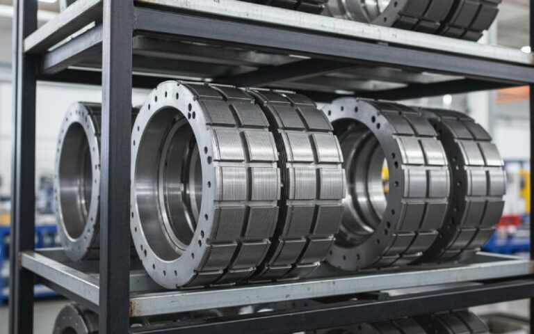
Let Sino's Lamination Stacks Empower Your Project!
To speed up your project, you can label Lamination Stacks with details such as tolerance, material, surface finish, whether or not oxidized insulation is required, quantity, and more.
Short answer: for the same electrical skew angle and machine geometry, skewing the stator or the rotor cuts cogging torque by almost the same amount. The big differences are cost, manufacturability, and side-effects on torque and losses, not raw cogging reduction.
A lot of the academic work treats skew as a generic knob. Skew stator stack, skew magnets, skew rotor bars, the equations hardly care. So if the physics is almost symmetric, why does the industry keep skewing rotors more than stators?
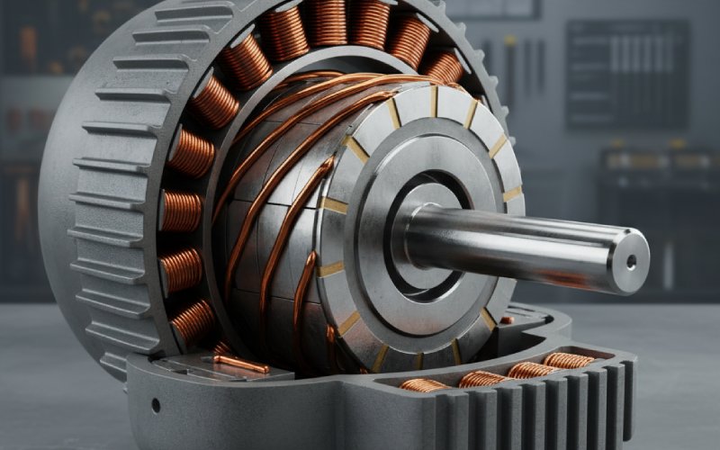
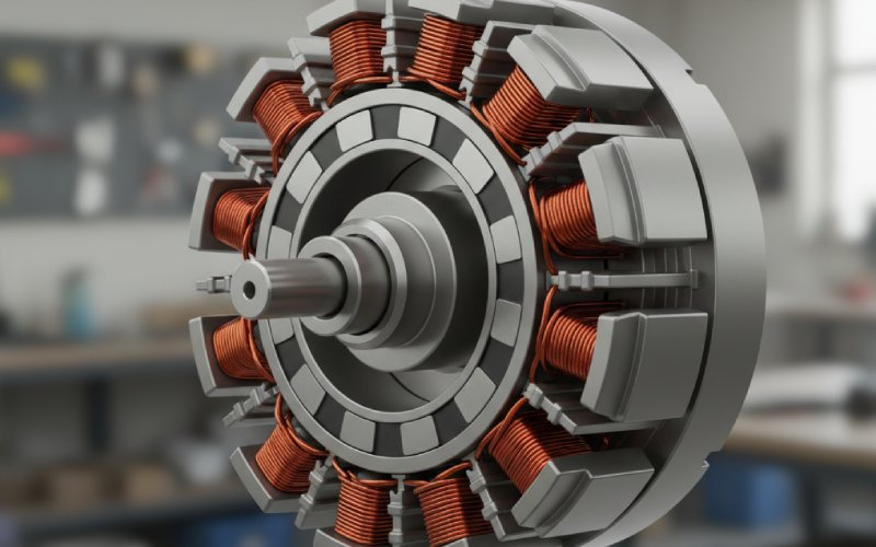
Cogging comes from the interaction between permanent magnet poles and stator teeth. You already know that. What matters for skew is simple but easy to ignore in design meetings:
If you imagine slicing the machine axially into many thin “mini-motors”, skew just rotates each slice slightly in electric angle. The total cogging torque is the vector sum of all those slices. If you skew by one cogging period, the main cogging harmonic can be driven almost to zero, because each slice is at a different phase and they cancel.
That’s why full slot-pitch skew is so effective: you spread one slot-related harmonic over a complete 360° phase span along the stack, turning a big sinusoid into almost flat noise. Whether the skew comes from the rotor or the stator doesn’t change that phasor picture as long as:
The mechanical skew angle is the same.
The skew is reasonably uniform along the stack.
You haven’t introduced some weird saturation asymmetry.
So on a clean, simulated model, rotor skew and stator skew with the same skew angle will give nearly identical cogging-torque curves and similar cuts in torque ripple. Modern studies on axial-flux and surface-mounted PM machines confirm that both stator-slot skew and magnet skew yield comparable percentage reductions when tuned to the same electrical angle, often 60–70% or more, and up to about 73% with advanced double-skew layouts.
The real split happens when you step away from the field plot and into the factory.
Here’s the trade in a compact form first, then we’ll unpack it.
| Aspect | Rotor skew | Stator skew |
|---|---|---|
| Typical use | Squirrel-cage induction motors, PM rotors with discrete magnets, many industrial BLDC drives | Modular stators, linear and axial-flux machines, some surface-mount PM motors |
| Cogging reduction (for same skew angle) | Essentially equivalent to stator skew; differences are second-order and topology-dependent | Essentially equivalent to rotor skew; differences are second-order and topology-dependent |
| Manufacturing | Change rotor laminations or bar slots; usually easier to wind and slot the stator | Skewed slots complicate coil insertion, tooling, and quality checks; slot area effectively shrinks |
| Impact on copper | Little direct impact on stator slot fill; end-winding still normal | Lower slot-fill factor and more awkward coil geometry; extra copper or higher loss for same ampere-turns |
| Impact on magnets | May require segmented or skew-magnetized magnets; higher magnet cost and assembly complexity | Magnets remain simple; skew lives in the steel and slots |
| Efficiency and torque | Lower fundamental torque and winding factor just like stator skew; potential extra magnet eddy losses with advanced skew patterns | Same torque penalty for a given electrical skew; more impact from extra copper loss due to packing limits |
| When it tends to win | High-volume induction motors, many radial PM motors where stator manufacturing is already tight | Machines where stator is modular or 3D-printed, linear/axial machines needing teeth shifting, or when the rotor is mechanically constrained |
Notice what’s missing in that table: there is no “this one always kills more cogging torque.” For the same electrical skew angle, the cogging reduction is mostly a wash.
There’s a good reason EASA’s design guidance talks about skewed squirrel-cage rotors as the normal case and notes that skewing the stator is less common: skewed stator slots make coil insertion harder and reduce the effective slot opening and cross-section. That is a real manufacturing pain, not just a footnote.
Once your stator is skewed:
The slot wedges become non-trivial parts, not off-the-shelf.
Automatic coil insertion equipment either needs special tooling or is off the table.
Quality control for insulation clearances and partial discharge gets trickier.
Rotor skew, in contrast, is often “free” once you’ve committed to custom rotor laminations or die-casting. You just twist the slot pattern in the punching. No extra winding gymnastics.
That’s why you see:
Induction motors with skewed rotor bars as standard practice to tame noise and torque ripple.
PM machines with skewed magnets or step-skew rotors in both radial-flux and axial-flux formats, especially where noise is a selling point.
So if you’re building a conventional radial-flux industrial motor, and you’re free to choose, skewing the rotor is usually the first knob to try. Not because it magically removes more cogging, but because it solves the same problem with less pain.
There are designs where touching the stator is actually easier, or where you want to keep the rotor as simple and mechanically robust as possible.
Linear flux-switching PM machines are a good example. A 2018 MDPI study compared several stator step-skewed structures (three-step, two-step, and an improved two-step) and used them to cut the cogging-force component that behaves just like cogging torque in rotary machines. In that architecture, the stator is built from modular sections anyway, so shifting or skewing those sections is straightforward.
Similar story in axial-flux machines using modular stator teeth. Some recent work shows that shifting opposite stator teeth by an optimal angle can significantly reduce cogging without needing exotic rotor work. If your stator already consists of individually mounted teeth, mechanically offsetting them may be the least intrusive change.
Stator-side tricks also shine when:
The rotor is a solid safety-critical piece (for example in high-speed machines) and you want as few cuts, steps, or segmented magnets as possible.
You are already slotting and assembling the stator in a way that makes small tooth displacements or step skew almost free.
You want the option to “tune” skew late in development by swapping stator modules rather than re-tooling the rotor.
In those cases, a stator skew or tooth shift can give you the same drop in cogging torque as rotor skew, while keeping the rotor simple and strong.
Theory says: skew by exactly one cogging period and you kill that harmonic. Practice says: you pay for it.
Skewing reduces the effective winding factor for the fundamental, which means lower torque per ampere. The more skew, the bigger the penalty. That’s why detailed studies on rotor and magnet skew often land around partial skew, typically a fraction of a slot pitch, balancing cogging reduction against torque loss and efficiency.
Recent work goes a bit more creative:
Segmented or “step” skew, where the rotor or stator is divided axially into two or three steps, each shifted by a fraction of the slot pitch. The machine behaves like several small motors bolted together, and you choose the step angles to cancel the worst harmonics while keeping tooling simple.
Double-skew magnets, especially in axial-gap motors, where magnet segments are skewed in two directions. One 2025 study reports around 73% reduction in cogging torque and about 60% reduction in torque ripple with such patterns, at the cost of more complex magnetization and higher manufacturing effort.
Unequal rotor-slot arcs and tooth notching used together with modest skew so you don’t have to lean too hard on the skew angle alone.
None of those results depend strongly on whether the skew is placed on the stator or rotor; they depend on how closely your mechanical skew approximates the ideal electrical phase distribution for the offending harmonics.
So “how much skew is enough” is usually answered by your optimization loop: you sweep skew angle in finite-element analysis, map cogging torque and average torque versus angle, and then pick the best compromise. Whether you move the stator steel or the rotor steel is almost a separate conversation.
If you strip away brand language and just treat this as an engineering choice, the decision process ends up looking like this, in words rather than a checklist.
Start with your manufacturing constraints. If the stator is already design-limited for slot fill, insulation clearances, and automated winding, you usually don’t want to twist its slots. That points you toward rotor skew, which aligns with what most industrial designs do.
Look at the rotor next. If your rotor is a simple stack of laminations for an induction motor or a PM rotor with discrete surface magnets, skew is straightforward: adjust the lamination slot pattern, or segment the magnets and step-skew them. The magnetization fixture or die-casting tool changes once, and you are done.
If the rotor is mechanically constrained or too expensive to touch – think high-speed solid rotor, complex interior PM pattern, or existing tooling you cannot change – then you move the skew to the stator side, especially if the stator is modular or already segmented.
After that, you treat skew as just one cogging-control mechanism among several. Slot/pole combinations, magnet pole-arc optimization, tooth notching, anti-cogging current injection, all of those can work together. Skew takes the edge off the geometry; control can then handle the remaining torque ripple without fighting a huge periodic disturbance.
The key thing is to avoid thinking “rotor skew = strong reduction, stator skew = weak reduction” or the other way round. For the same skew angle, they are nearly interchangeable from the cogging-torque standpoint. What changes is everything around them: winding factor, manufacturing, copper usage, magnet cost, and sometimes mechanical integrity.
If you only care about the amount of cogging torque reduction and you keep the skew angle and machine topology fixed, there is no consistent winner. Stator and rotor skew give almost the same percentage reduction in cogging torque; the differences are small and case-specific.
If you care about the total design – cost, manufacturability, torque density, losses – then:
Most conventional radial-flux motors skew the rotor because it is easier to manufacture and less hostile to winding and slot fill.
Stator skew or tooth shifting becomes attractive when the stator is modular or easy to adjust, or when the rotor is mechanically or commercially “off limits”.
And if you’re already pushing hard with advanced skew patterns, segmented rotors, or sophisticated tooth layouts, the choice of stator versus rotor is usually locked in by how your production line is built, not by an extra few percent of cogging-torque reduction.
So the honest answer to the title question is slightly boring but very useful: skew whichever side your process can twist more cheaply, then spend your design time optimizing the skew angle and the rest of the geometry. That is where the real gains are hiding.