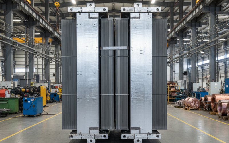
Let Sino's Lamination Stacks Empower Your Project!
To speed up your project, you can label Lamination Stacks with details such as tolerance, material, surface finish, whether or not oxidized insulation is required, quantity, and more.
Let’s talk about what actually changes in the core when you move to a well-designed step-lap CRGO lamination stack… and where engineers quietly lose the benefit on the shop floor.
At the joint, three things matter more than the brochure drawings admit:
Step-lap joints distribute the joints over several staggered overlaps instead of one single plane. Industry and academic work both show that, for a given steel grade and geometry, step-lap joints reduce no-load loss, excitation current, and sound pressure level compared with butt-lap or simple miter joints.
But that statement is almost useless without the details.
You don’t reduce core loss “because step-lap is modern”. You reduce it because you control a small set of geometric and process variables.
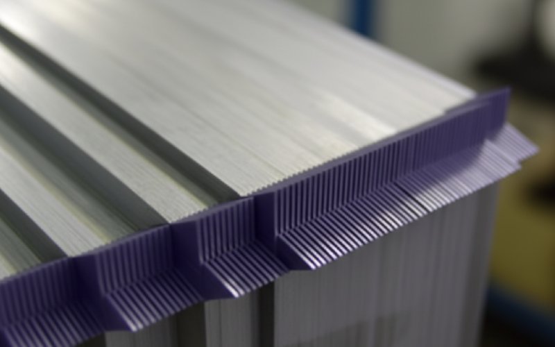
Step-lap is essentially a controlled 3D air-gap pattern.
Design and test work on wound and stacked cores shows clear sensitivity of loss to lap length and number of laminations per step. There is usually a relatively flat optimum band rather than one magic value, and it shifts with lamination thickness and operating flux.
In practice, you’ll often see:
Multi-step-lap joints behave nicely up to a point – then not.
What this means in design language:
You know the building-factor game:
For a lamination supplier, this is where value quietly leaks: every time assembly switches from single-sheet to double-sheet without the designer adjusting the stack calculation, real no-load loss drifts away from the drawing.
The noise story is mostly magnetostriction and how the joint geometry modulates it.
Field data and lab measurements agree on a rough range:
At low and medium inductions, multi-step-lap joints clearly reduce noise compared with miter or simple overlap. At higher inductions, the improvement shrinks and can flatten out, as some tests on model cores have shown.
It’s not just “more steps = quieter”.
So, if your acoustic problem is a narrow resonance in the tank, the right step pattern helps. If the problem is poor clamping or gaps, no geometry trick will save you.
Several industrial guides point out the same thing in different words:
The noise benefit of step-lap is strongly dependent on cutting accuracy, burr control, and assembly alignment.
Misaligned steps, bent laminations, or uneven clamping reintroduce stress and small air gaps right where step-lap is trying to smooth the flux.
You can treat step-lap lamination design as a small parameter study instead of an art form.
| Design lever | Typical choice for CRGO cores | Effect on no-load loss (qualitative) | Effect on noise (qualitative) | Practical notes for lamination stacks |
|---|---|---|---|---|
| Number of steps | 5 steps for small/medium units; 7 for high-performance cores | 5 vs miter: ~2–4% lower total core loss in tests | Multi-step generally quieter than single-step | Beyond 7 steps, gains are small vs stacking complexity |
| Step increment (per step) | 2–6 mm overlap change per step | Too small: local saturation; too large: more stray flux | Poor patterns can worsen certain harmonics | Make sure your press line can hold ±0.2 mm on lengths |
| Lap length at corner | Optimized from prototypes; often a few times lamination thickness | Drives joint losses strongly if mis-sized | Changes vibration distribution near corners | Specify as a range plus measurement method, not just a nominal value |
| Assembly method (single vs double) | Single-sheet “books” for low-loss designs | Single < double, due to better building factor | Indirect effect (via gaps and stress) | Confirm assembly style in RFQ; don’t assume the factory choice |
| Lamination thickness | 0.23–0.30 mm CRGO for distribution cores | Thinner → lower eddy loss; more plates to stack | Minor direct effect; mostly via induction and gaps | Combine with step-lap to hit loss targets with margin |
| Max flux density in limb (Bmax) | Often 1.6–1.7 T for CRGO designs | Above a design-specific “critical induction”, losses jump faster in step-lap joints | Higher B increases magnetostrictive forces | Don’t “spend” all B margin assuming step-lap will fix noise |
| Clamping pressure and pattern | Distributed clamps at yoke corners and limbs | Affects residual gaps in joint and stack | Strong link to vibration of core and tank | Ask for documented clamping procedure with torque values |
| Burr and coating control | Low burr, consistent insulating coating | Poor burr control ruins interlaminar insulation | Extra friction can damp or worsen vibration, case by case | Often the real reason two “identical” designs sound different |
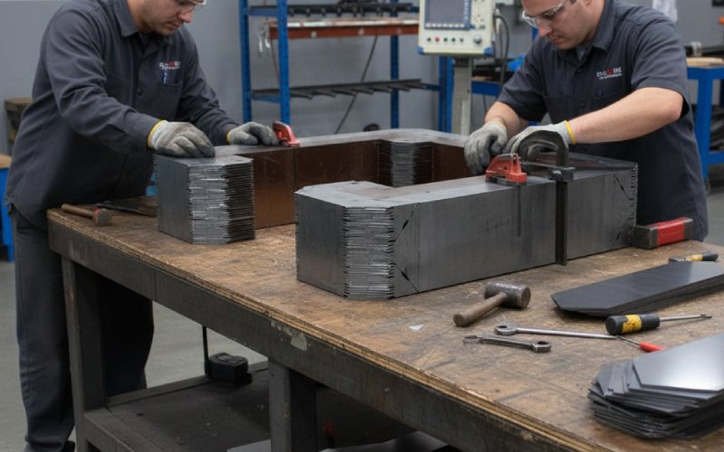
On paper, step-lap is geometry. On the shop floor, it’s mostly sequence and discipline.
Key spots where lamination stacks decide your real loss and noise:
If you buy loose lamination stacks rather than finished cores, these points belong partly to your supplier and partly to your transformer factory. The interface is where problems usually show up.
If you want the benefits, you have to ask for them precisely.
Suggested items to spell out in an RFQ or technical specification for step-lap CRGO lamination stacks:
This is how a lamination stack stops being a commodity and starts being a controllable part of your loss and noise budget.
Take a 1 MVA, 3-phase, 3-limb stacked core at around 1.65 T in CRGO.
From published comparisons of miter vs 5-step-lap joints for similar cores:
For a core originally at 1600 W no-load loss:
On noise:
Treat those numbers as order-of-magnitude guidance, not guarantees. The actual spread between drawings and test reports usually comes from the manufacturing bullets in section 5.
Use this list as a quick filter when reviewing drawings, offers, or factory proposals:
If any of these are missing, the phrase “step-lap CRGO lamination” on a quotation doesn’t tell you very much.
Not automatically. The evidence shows step-lap gives lower loss when the step pattern, overlap length, and stacking quality are optimized. Poor patterns or sloppy assembly can erase the advantage or even increase loss at high inductions.
For most distribution and small power transformers, 5 steps are a solid default: good balance between performance and manufacturing effort. 7 steps can give a small additional loss reduction but adds complexity; 3 steps are usually a compromise you’d only accept with proven test data.
Sometimes, but you need to re-check:
Stack height and window dimensions
Core loss at rated B on a prototype or detailed simulation
Clamping hardware alignment with the new joint pattern
Without that, you’re guessing. Step-lap joints can have slightly different corner volumes and may shift hot-spot locations.
Yes. High-grade CRGO or amorphous steel reduces material losses; step-lap improves how the flux crosses joints and often still gives measurable gains in both loss and noise, especially at higher inductions where joint behavior dominates.
You don’t need a completely different standard, but you should tighten a few items:
Stricter limits on cutting tolerances and burr height
Explicit step pattern and lap length limits proven on noise tests
Clamping instructions that control pressure distribution at joints
Noise-focused research and guides repeatedly show that step-lap geometry and assembly tolerances strongly influence acoustic performance.
Ask for numbers from a comparable design:
No-load loss and excitation current at rated B
Measured sound pressure level and test conditions
If they can provide real data from step-lap cores built with similar steel, flux density, and size, you know “multi-step-lap” means a specific, controlled design rather than a label on a drawing.