Let Sino's Lamination Stacks Empower Your Project!
To speed up your project, you can label Lamination Stacks with details such as tolerance, material, surface finish, whether or not oxidized insulation is required, quantity, and more.
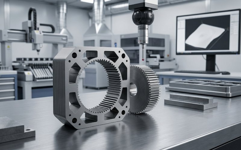
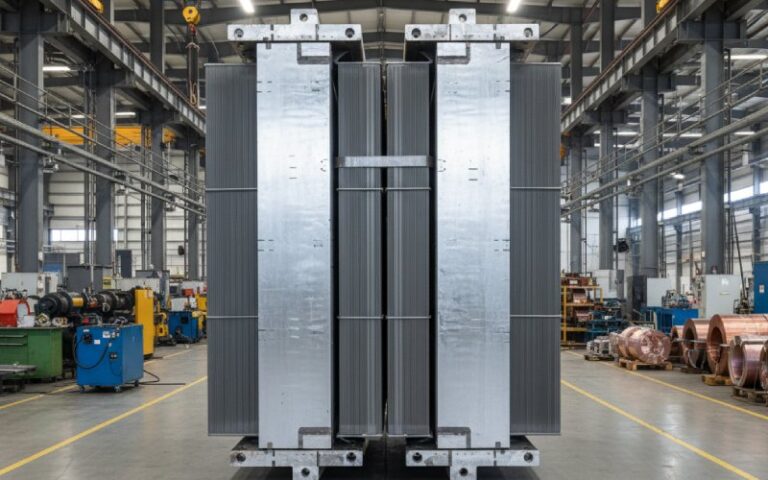
If you are sourcing stepper motor laminations, the “layered” look is not the interesting part. The useful question is what those layers do to loss, torque consistency, stack accuracy, and production repeatability. In hybrid stepper motors, the rotor itself is built around two toothed rotor sections with an axial magnet between them, and those toothed sections are mechanically offset by half a tooth pitch. So the layered look is not one detail. It is a package of magnetic and manufacturing decisions that has to survive real production, not just CAD.
We manufacture custom stepper motor lamination stacks for buyers who already know the basics and want fewer surprises between prototype and volume production. That is where most problems start. Not in theory. In the cut edge. In the stack join. In the way a drawing ignores what punching or welding does to the steel.
Stepper motor laminations are built from thin insulated electrical steel sheets instead of a solid steel core because laminations reduce interlaminar and eddy-current loss. The insulation coating on both sides of the sheet helps block current between layers, while the thin-sheet structure limits unwanted circulating currents that would otherwise create extra heat and loss. For motor cores, non-oriented electrical steel is commonly used because it fits rotating magnetic conditions better than directional sheet materials.
That is the standard explanation. The sourcing explanation is different.
A layered core also gives us a way to control tooth geometry, slot profile, stack height, and rotor/stator repeatability from batch to batch. In stepper motors, especially small hybrid designs, tiny geometric drift turns into angle error, torque scatter, noise, or extra heating much faster than many buyers expect. The smaller the machine, the less room there is to hide edge damage from cutting.
For custom stepper motor lamination stacks, material selection usually starts with non-oriented electrical steel in thin gauges used for motor cores. A commonly referenced thickness range for motor laminations is about 0.2 mm to 0.65 mm, but the right gauge depends on switching conditions, loss target, tooling route, forming stability, and how much stack factor you are willing to trade for insulation and assembly needs. Thinner is not automatically better. Not after cutting damage shows up.
What we look at before recommending a material is simple:
If the material decision is made too early, without the process route, the project usually pays for it later.
We do not quote from outline geometry alone. We review tooth width, bridge area, slot ratio, stack height, fit features, burr direction, joining area, and whether the design will move from laser-cut samples to progressive stamping later. A lamination that looks easy to cut can still become unstable in stacking, or drift once the joining method changes.
For quotation, we usually ask for:
| Item | Why we ask for it | What it changes |
|---|---|---|
| 2D drawing / DXF | Defines tooth profile, slots, notches, OD/ID | Tooling route, feasibility, inspection method |
| Stack height | Determines lamination count and join strategy | Compression method, stack tolerance, cost |
| Annual volume | Separates prototype logic from mass production logic | Laser cutting vs. stamping, die investment |
| Material request | Sets magnetic and manufacturing baseline | Loss, punchability, coating, price |
| Rotor or stator use | The same steel behaves differently in different geometries | Burr sensitivity, alignment priority |
| Joining preference | Interlocking, welding, bonding, or mixed route | Magnetic loss, strength, lead time |
For early samples, laser cutting is often the fast route. It avoids die lead time and lets buyers validate fit, assembly logic, and early motor behavior. But it is not the same thing as volume production. Laser cutting changes the edge with a thermal mechanism; stamping changes it with a mechanical one. Those are not equivalent. So if a project will move to progressive stamping later, we flag that from day one instead of pretending the prototype edge condition will tell the whole story.
This matters more in small stepper laminations. The damaged zone near the cut edge takes up a larger share of the tooth width, which means performance drift between sample and production can show up earlier than expected.
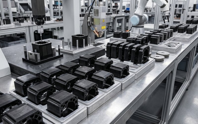
Once annual volume and geometry justify tooling, progressive stamping becomes the stable route for custom stepper motor laminations. It gives better throughput, lower part cost at volume, and tighter consistency lot to lot. But the die condition now becomes part of the motor design whether anyone writes that down or not. Punch clearance, punch wear, strip flatness, and coating handling all change the final core.
For this reason, our production review focuses on three things before release:
If not, we correct there. Not after shipment.
This is one of the first places we separate serious projects from cheap ones.
Punching electrical steel changes the magnetic properties near the cut edge. Reviews of electrical steel manufacturing effects report that punching can reduce average torque and increase core losses, and the effect is especially relevant in smaller electric machines where the affected edge zone occupies more of the active section. Burrs also create practical trouble: stack height drift, fit issues, and interlaminar short paths once the core is clamped or welded.
We treat burr control as a magnetic issue and a dimensional issue at the same time. That means:
A lamination stack is only partly a cutting job. The rest is joining.
The main joining routes for electrical steel laminations are mechanical joining, fusion welding, and glue or bonding methods. Each route solves one problem and creates another. Welding gives strength and handling stability. Mechanical interlocking is efficient for production. Bonding keeps electrical isolation more uniform and usually treats magnetic performance more gently, but it adds material and process control demands. Reviews of joined electrical steel stacks note that joining can degrade magnetic properties by damaging the insulation coating, changing microstructure, adding residual stress, or creating interlaminar conductive paths. Adhesive joining often shows lower deterioration in iron loss and exciting current than welding, but it can raise cost and service-temperature concerns depending on design and loading.
Here is the short version buyers usually need:
| Joining method | Main advantage | Main risk | Typical use in sourcing decisions |
|---|---|---|---|
| Interlocking | Good production speed, no added adhesive step | Local strain, local short risk, stack-factor tradeoff at lock points | Volume programs where cost and throughput matter |
| Welding | High mechanical integrity, good handling in assembly | Heat-affected zone, insulation damage, residual stress | Stacks that need stronger handling or later machining |
| Bonding | Better electrical isolation between laminations, quieter stack | Adhesive control, cure control, added cost | Projects that prioritize magnetic cleanliness and lower vibration |
| Mixed route | Balances strength and magnetic performance | More process variables to manage | Designs that cannot rely on one method alone |
We do not push one joining route for every motor. We match the route to the drawing, the stack height, the rotor or stator function, and the buyer’s production target.
Not sure which joining method fits your project? Send the drawing and target volume. We can review the tradeoff before tooling starts.
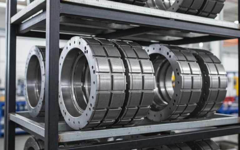
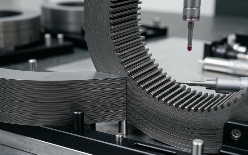
For hybrid stepper motor rotor laminations, stack accuracy is not only about height. It is also about tooth registration. The hybrid rotor structure uses two toothed rotor sections with axial magnetization and a half-tooth-pitch mechanical offset between the two rotor sections. That offset is part of the stepping behavior, not a cosmetic detail. When the alignment slips, the motor may still run, but stopping accuracy, torque smoothness, and consistency from unit to unit start drifting.
This is why we treat hybrid stepper rotor stacks differently from generic motor cores. The stack build has to protect both magnetic intent and mechanical indexing.
This point deserves its own section because it causes repeat trouble.
A laser-cut prototype can be the right first step. Fast. Flexible. Useful. But it should not be sold to the buyer as a perfect prediction of stamped production. Punching introduces mechanical edge strain. Laser cutting introduces thermal edge effects. Clamping and joining then add another layer of change. Research on electrical steel manufacturing effects and joining behavior shows these steps can alter permeability, torque, loss, and heating enough to matter in real machines.
Our rule is plain: if the project will scale, we talk about the scale-up route while the prototype is still being discussed.
For custom stepper motor lamination stacks, lead time usually depends less on the lamination outline than buyers think. The larger drivers are:
If you want a faster quotation, send these at the start: drawing, material request, stack height, annual volume, prototype quantity, and whether you need rotor stacks, stator stacks, or both.
Motor laminations are commonly made from thin non-oriented electrical steel with insulation coating on both sides. The exact thickness and grade depend on loss target, tooling route, and stack design.
Because a solid core allows larger circulating currents and higher loss. Laminated construction reduces interlaminar current paths and helps control heat and efficiency.
Yes, for early samples and geometry validation. But laser-cut samples should not automatically be treated as identical to stamped mass-production parts, because the edge condition is created in a different way.
There is no universal best method. Welding gives strength. Interlocking helps production efficiency. Bonding often protects magnetic performance better, but it adds adhesive and curing control. The right choice depends on stack height, handling needs, loss target, and production volume.
Because burrs do more than affect appearance. They can disturb stack height, interfere with assembly, and create short paths between laminations. In smaller motors, cut-edge damage takes up a larger share of the active section, so the effect can show up faster.
We recommend sending the 2D drawing or DXF, stack height, material request, annual volume, prototype quantity, and the preferred joining method if already defined.
Yes. For most projects, the better path is to review both stages together so the prototype route does not drift too far from the production route.
If you are sourcing a stepper motor laminations manufacturer for rotor laminations, stator laminations, or complete lamination stacks, send us your drawing and project targets.
We can review:
Send your RFQ today for a drawing review and manufacturing feedback on your custom stepper motor lamination project.