Let Sino's Lamination Stacks Empower Your Project!
To speed up your project, you can label Lamination Stacks with details such as tolerance, material, surface finish, whether or not oxidized insulation is required, quantity, and more.
Most “mystery tones” in e-machines are just a bookkeeping failure: the tooth-force harmonic is indexed one way, the structural modes another, and the rotor path gets ignored because the stator is easier to blame. Put everything on the same axes—frequency, spatial order, and where the load actually closes—and the link usually shows itself.
If your “tooth force” is really airgap pressure on a convenient surface one day, then nodal forces on tooth tips the next, you can make any mode look responsible. The force definition is the contract. Break it and your modal correlation becomes a storytelling exercise.
Also, the boring detail that matters: force accuracy is mesh-sensitive, and people quietly ship bad force maps into structural solvers. One pragmatic check is to compare torque from the mapped forces against the solver’s torque; when they match, you’re at least not violating conservation in a loud way.
Separate note. If you’re comparing methods (virtual work vs Maxwell stress on different surfaces), you’re not being academic. You’re trying to stop a 3 dB argument from turning into a 15 dB mistake.
Force frequency alone is half a label. The other half is the spatial pattern around the airgap: circumferential wavenumber (often written as r). If you don’t carry r through the pipeline, you’ll “match” a peak to the wrong mode because a lot of modes sit near the same frequency band.
The tooth-FRF community is blunt about this: magnetic forces are distinguished by frequency and spatial distribution, and that spatial distribution is the circumferential wavenumber. They even give the sanity anchors: r = 0 is a pulsating wave, r = 1 corresponds to unbalanced magnetic pull (UMP).
There’s an old rule that keeps surviving because it’s true: strong radiation happens when the excitation frequency is near a natural frequency and the spatial order lines up with the mode shape. Not optional. Two locks.
The jump from “tooth force” to “rotor mode” is not mystical coupling. It’s load closure.
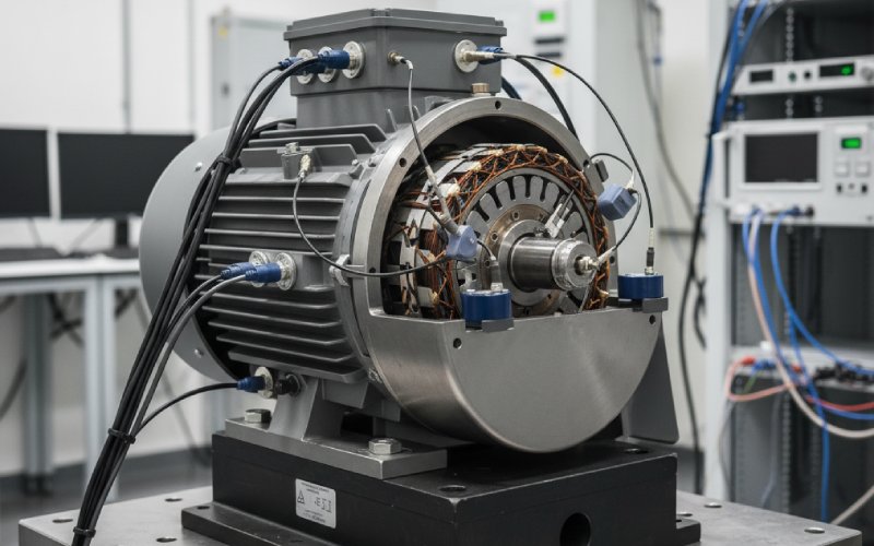
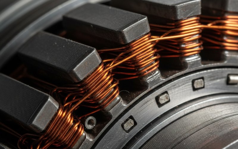
A big chunk of tooth force content is radial and lives in the stator. That’s the standard story and it’s often correct: stator vibrations driven by electromagnetic forces in the airgap radiate as the exterior surface moves, and resonances occur when force harmonics sit near vibration modes.
But some harmonics don’t just shake teeth. They create a net resultant on the rotor, or a net moment, or they modulate bearing reactions. The cleanest example is r = 1: UMP acts like a lateral force vector rotating with the field/eccentricity pattern, and it routes straight into rotor bending dynamics through the bearings.
Burakov’s UMP framing is useful because it’s a spectral statement, not a vibe: rotor eccentricity produces additional field harmonics shifted by ±1 in spatial order, and UMP comes from interactions meeting that ±1 relationship. That’s the rotor path announcing itself in the index math.
Then there’s the tangential side. People underweight it. A recent eAxle study correlates torsional vibration/noise with the tangential electromagnetic force array and treats radial vs tangential contributions explicitly. If your “acoustic noise” peak is tied to a torsional mode and you only carried radial tooth forces, you already decided the answer.
You don’t need a grand coupled model to do the linking. You need disciplined artifacts and consistent indexing.
| Artifact you keep | How you get it | Why it matters for rotor-mode linking | A quick consistency check |
|---|---|---|---|
| Tooth force spectra, radial and tangential, with phase | EM solve → per-tooth forces → FFT per operating point | Rotor coupling depends on spatial order and phase, not just magnitude | Torque reconstructed from forces tracks EM torque across the sweep |
| Circumferential wavenumber r for each significant harmonic | Spatial FFT around the airgap / teeth | Rotor and stator modes “select” spatial orders; wrong r means wrong culprit | If r = 1 content is large, expect UMP-like bearing loads to show up |
| Net airgap force and moment on the rotor | Integrate Maxwell stress/forces into global resultants | Rotor bending cares about net lateral loads and moments, not tooth-local forces | Resultant direction rotates/behaves like the predicted wave pattern |
| Bearing reaction forces (measured or modeled) | Structural model or test-derived transfer | Bearings are the bridge between airgap forces and rotor modes | Peaks in bearing force FRFs coincide with rotor bending/torsion modes |
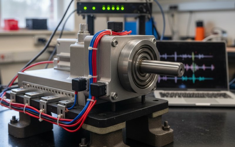
| Rotor modal set with shapes (bending/torsion) and damping assumptions | Rotor-only or rotor+shaft FE/modal test | You need mode shape participation to explain which tones radiate | Order tracking shows tone peaking near rotor eigenfrequencies |
| Tooth FRF → wave FRF mapping when you’re in test mode | Excite teeth, measure housing response, convert to wave basis | Lets you project operational forces onto structural waves, then onto modes | Wave FRF gives modal extraction leverage without full FE detail |
That table is the whole game. Not every row is needed every time, but when a link is disputed, the missing row is usually the one that would settle it.
Treat “match” as a filter, not a proof.
You look for a force component at frequency ( f_k ) with circumferential wavenumber ( r_k ). You look for a rotor mode with natural frequency near ( f_k ) and a compatible circumferential order (nodal diameter / lobes) that can accept ( r_k ). Sometimes the rotor mode label is or . Different dialect, same idea.
If you skip spatial order, you’ll correlate the 2.9 kHz tone to whichever stator mode is closest. If you carry spatial order, you’ll notice the tone is picky about where it radiates, where it’s sensed, which bearing sees it first.
Order tracking can do a lot with almost no modeling. The NASA rotor-vibration report uses the fundamental electrical frequency relation and marks harmonics; peaks clustering around a rotor eigenfrequency while following an electrical harmonic order is a strong hint that EM excitation is feeding a rotor resonance.
Tooth FRF concepts also scale better than people admit. The ISMA paper’s move—characterize structural response by exciting stator teeth, convert tooth FRF to wave FRF, then analyze rotating Maxwell stress waves—makes “spatial order” measurable, not just simulated. They even discuss extension toward rotor FRF thinking, which is where rotor-mode blame stops being speculative.
NASA’s “Scorpion” motor data is a clean case because it names the rotor modes and shows the acoustics. Peak acoustic radiation sits near 3000 Hz; it peaks at specific motor speeds (6292 and 6441 rpm in that report), the peak corresponds to the fourth electrical harmonic at those speeds, and the tone aligns with the rotor ((2,1)) mode from FEA (with experimental frequency nearby). That’s “tooth/EM forcing” meeting “rotor resonance” in public, with numbers.
If your competitor content stops at “stator vibrations cause noise,” this is the missing chapter: the forcing can be electromagnetic and still be routed through rotor modes, with directivity patterns and sensor-to-sensor deltas that a stator-only story can’t match.
If the link is “force harmonic exists” → “rotor mode accepts it” → “bearing path transmits it,” then you have three levers, and mixing them blindly wastes time.
You can reduce the harmonic content in the tooth forces. Slot/pole choices and tooth-modulation effects shift what harmonics exist and how strong they are; one recent PMSM study explicitly compares slot counts and shows major harmonic components aligning with natural frequencies in NVH results, which is basically a resonance map in disguise.
You can move the rotor mode. Stiffness, mass distribution, end-bell participation—whatever changes the rotor eigenfrequency or damping—works when the excitation order is hard to eliminate. That NASA report leans on exactly this logic: peak radiation occurs when operating speeds excite rotor resonance modes.
You can weaken the transmission path. Bearings and supports are not neutral; they decide whether rotor vibration shows up on the radiating surfaces. And when the root driver is UMP-ish content, remember UMP is sensitive to eccentricity-driven harmonic interactions; Burakov also notes parallel paths and rotor cage effects can reduce UMP in some configurations, which is an electromagnetic-and-circuit-side “path” lever people forget exists.
| What you observe | What it often implies about r | Rotor involvement likelihood | What to check first |
|---|---|---|---|
| A tone tracks an electrical harmonic order across speed, then spikes hard in a narrow speed band | The spatial order is compatible with a specific structural mode, not just “anything” | High if the spike aligns with a rotor eigenfrequency and shows bearing sensitivity | Overlay electrical harmonic orders with rotor modal frequencies and bearing FRFs |
| A strong 1×-like lateral vibration appears under conditions where mechanical unbalance is ruled out | r = 1 (UMP-like) content is present | High because UMP loads go straight into rotor/bearing dynamics | Compute/estimate net lateral EM force vector and compare phase with shaft motion |
| Noise changes when skew/segmentation strategy changes, while radial force metrics barely move | Tangential force structure is changing, not just radial | Medium to high if torsional modes are near the tone | Decompose radial vs tangential force arrays and correlate with torsional response |
| Housing surface acceleration is modest, but end-bell or shaft-adjacent microphones see a sharp tone | The radiating surface is tied to rotor/end structure participation | High, especially with directional radiation | Compare acoustic directivity / sensor placement sensitivity against mode shapes |
One last remark, because it saves weeks: if your force spectrum and your modal database don’t share the same spatial language, the “link” will look random. It isn’t random. It’s mislabeled. Carry ( f ) and ( r ), keep phase, and make the bearings part of the story from the start.