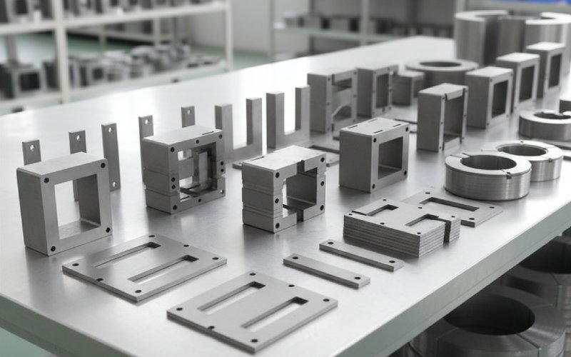
Let Sino's Lamination Stacks Empower Your Project!
To speed up your project, you can label Lamination Stacks with details such as tolerance, material, surface finish, whether or not oxidized insulation is required, quantity, and more.
This article is about the part everyone skips: how the lamination stack you choose quietly decides losses, noise, and manufacturing pain.
We’ll stay practical and a bit blunt: EI, UI, step-lap, and wound cores as they show up on real purchase orders.
Very short recap, just to sync vocabulary:
Everything else in this article assumes you’re comfortable with flux density, magnetostriction, and loss separation. So we’ll go straight to trade-offs.
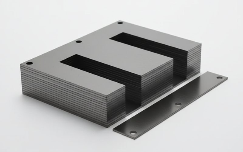
Most designers start from EI not because it’s “best”, but because the ecosystem around EI is mature:
What EI stacks usually give you
Where EI starts to look tired
What to watch when buying EI lamination stacks
If you’re sourcing from multiple lamination factories:
EI is still the default choice when your KPI spreadsheet is led by purchase price, reasonable efficiency, and easy local sourcing.
UI cores usually show up in projects where the winding shop says:
“We want to wind the coils separately and then just drop them on.”
That’s the UI story in one sentence.
Why people move from EI to UI
But you pay for this in other currencies
From a lamination-stack point of view, UI is just another stamping set, but your whole mechanical layout changes. Procurement needs to think about matching UI series (UI-30…UI-100 etc.) to planned winding tooling.
If most of your production is still EI, flipping one product family to UI can increase complexity: extra tooling, extra stock keeping units, separate QA jigs. Sometimes worth it; sometimes not.
Step-lap isn’t a shape; it’s a stacking method for the joints.
Instead of one abrupt transition where the limbs meet the yokes, you have several short overlaps arranged like stairs. Each lamination is shifted a little; flux sees a smoother path.
Studies and supplier data are consistent on a few points:
There’s a twist though: at equal core flux, no-load current and its harmonic spectrum can behave differently. One comparative test showed lower RMS no-load current for butt-lap than step-lap in a particular case, while the harmonic profile was actually worse for step-lap.
So step-lap is not magic. It shifts where and how you pay.
Cost and process impact
From a lamination-supplier quote, you’ll usually see step-lap yokes as a clear line item with higher price per kg than straight-cut yokes.
Where it makes sense:
Below roughly tens of kVA and with short annual operating hours, the step-lap premium often doesn’t pay back; for 24/7 utility gear it usually does, and quickly.
A wound core is built by spirally winding an electrical-steel strip (CRGO, amorphous, or nanocrystalline) into a closed loop, then cutting, annealing, and sometimes re-joining. Geometry can be rectangular, oval, or 3D triangular for 3-phase units.
Why manufacturers invest in wound-core equipment:
The technology has been pushed further with 3D wound cores for 3-phase transformers, giving more balanced magnetic circuits and still lower no-load losses and inrush currents.
What holds some factories back:
In practice, wound cores dominate in:
If you already run a lamination stamping business, moving into wound cores is almost a different industrial game.
Here’s a compact view for B2B decision-making. Treat the ranges as typical, not absolute.
| Aspect | EI lamination stacks | UI lamination stacks | Step-lap stacked cores | Wound cores |
|---|---|---|---|---|
| Magnetic path | Shell-type, joints at top/bottom yokes | Core-type, simpler single window | Same geometry as EI/UI, but joints split into several steps | Essentially continuous path, joints minimised or moved |
| Typical steel & thickness | CRGO M2–M5, 0.23–0.35 mm common | Similar to EI, often same grades | Usually high-grade CRGO to justify extra work | CRGO, amorphous, or nanocrystalline; 0.18–0.30 mm typical for power work |
| Core loss vs simple EI | Baseline | Similar, depends on joint details | Typically lower at same B and frequency, especially at joints | Often lowest for same rating, especially with amorphous steel |
| Noise behaviour | Acceptable if clamped well; joints are main source | Similar to EI | Better on average; smoother flux transition reduces hum | Usually very quiet; continuous path and low magnetostriction grades help |
| Manufacturing complexity | Lowest: simple stamping and stacking | Slightly more complex mechanics, similar stamping | Higher: precision cutting and stacking sequence | Highest: core winding, special annealing, cutting, dedicated tooling |
| Capex required at factory | Stamping press, shearing, annealing | Same as EI plus fixtures | Same as EI plus better cutting/stacking systems | Winding machines, large annealing furnaces, core handling lines |
| Where it typically shines | Control transformers, low–medium power distribution, general purpose power supplies | Power supplies, welders, drives, units needing easier coil assembly | Mid/large distribution transformers where efficiency and noise are tight | Utility distribution, high-efficiency and low-loss units, some metering CTs and special designs |
| Best argument to finance | Lowest lamination cost per kVA, broad supplier base | Balance of assembly cost and compactness | Reduced energy loss and noise penalties over transformer life | Strong total owning cost story, potential weight/material savings despite higher core price |
Most tenders or internal specs boil down to a handful of design drivers:
Let’s walk through a few common patterns.
Small control transformers, machine tool supplies, small isolation transformers.
Think: the same 3 or 4 ratings, produced all year.
Here you start to see:
The important thing is to standardise lamination stacks early and lock them into drawings, so procurement doesn’t start mixing similar-looking stacks from different suppliers with small dimensional or coating differences.
Once a utility or regulator attaches a cost to each watt of no-load loss, core construction moves closer to the top of the spec.
In this zone you normally see one of:
The right answer depends on your factory:
Hospitals, dense urban substations, some commercial buildings.
Engineers usually specify Bmax and steel grade; lamination specialists live in smaller details that make or break the result.
Some points worth writing into your specs or inspection plans:
Usually, but not automatically.
EI vs UI: core cost per kg can be similar; the difference comes from assembly time and mechanical fixtures. In some factories, UI ends up cheaper at system level.
EI vs wound: wound cores nearly always cost more per kg, especially with amorphous or nanocrystalline materials. But their lower core losses can more than compensate over life in 24/7 service.
You have to compare total owning cost for the specific project, not just lamination price.
Rough rule:
If the transformer runs most of the time and there is any tariff or penalty linked to core loss, step-lap or multi-step-lap joints are usually worth the premium, especially above tens of kVA.
For small transformers that run intermittently (for example, control transformers in machinery), the energy saved per year can be too small to justify higher lamination cost and complexity.
Not always.
A wound core in average CRGO can lose to a well-designed step-lap core in top-grade CRGO at the same flux density.
Amorphous or nanocrystalline wound cores typically beat stacked CRGO on no-load loss, but they bring other constraints (mechanical, cost, sometimes larger volume).
So the question isn’t “wound vs step-lap” in general, but which steel, which flux density, and which joint implementation.
Mechanically, maybe. Electromagnetically and thermally, usually no.
Switching between shell-type and core-type arrangements changes:
Leakage inductance
Stray losses in tank and clamping
Cooling paths
You’d normally at least re-do the core/winding layout and check losses and temperature rise. A simple like-for-like swap of lamination shape is risky.
At industrial power frequencies:
0.23–0.27 mm CRGO for high-efficiency and low-loss transformers.
0.27–0.35 mm CRGO or 0.35–0.50 mm CRNGO where cost dominates and loss penalties are soft.
Thinner laminations reduce eddy current loss but increase material and processing cost. Treat thickness as a variable in your optimisation, not a fixed number.
Technically you can; practically, it’s asking for variability.
Different suppliers may use:
Slightly different steel grades (even under the same label)
Coating systems with different resistivity and thickness
Different burr control and annealing
For non-critical products, it may be acceptable; for transformers where losses and noise are contractual, it’s better to keep each core to one controlled lamination source.