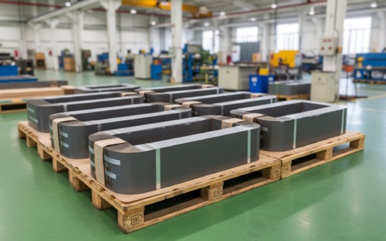
Let Sino's Lamination Stacks Empower Your Project!
To speed up your project, you can label Lamination Stacks with details such as tolerance, material, surface finish, whether or not oxidized insulation is required, quantity, and more.
No long theory here, just labels so we talk about the same things.
Ap = Aw · Ac, used by most core makers to rate power capability.Power-level formulas can always be pushed back to something of the form
Aw · Ac ∝ P / (Kw · Bmax · J · f)
for a chosen flux density, current density, frequency, and utilization.
So Ap gets you how big the core has to be. This article is about how to split that Ap between Aw and Ac when you order or design the lamination stack.
Take two lamination stacks with the same Ap:
Both satisfy the power equation on paper. They won’t behave the same once you wind, insulate, and ship them.
A few examples you probably recognise:
So when buyers send us drawings that just say “Ap ≥ X cm⁴”, it is half the story. The ratio sets how stressful life will be for copper, insulation, and lamination tooling.
A rough mental model that works quite well in lamination-stack discussions:
Once Ap is fixed by the power requirement, you slide along a line of solutions:
That’s all. The rest is you deciding which side of the problem you’d rather fight on.
Instead of absolute numbers (which bounce around with material and frequency), it’s usually more useful to talk about bias — designs that clearly favour Ac or Aw.
Below is a qualitative table you can slide into your spec discussions.
| Design bias | What it looks like in the drawing | Where it shows up | Main upside | What bites first |
|---|---|---|---|---|
| Core-heavy (Ac-biased) | Wide tongue / limb, short window height, narrow window width. Stack height looks modest but steel cross-section is generous. | Low-voltage, high-current units where copper is chunky and short; compact distribution transformers. | Lower magnetizing current, easier to keep Bmax low; often quieter at no-load; good where mains distortion is bad. | HV insulation squeezes out quickly. Harder to route leads. Winding shop complains about filling last layers. |
| Balanced | Window roughly proportional to limb width; aspect ratio of window between ~2:1 and 3:1; stack thickness similar to tongue width. | Most catalogue EI/UI lamination sets meant for “general purpose” power transformers. | Reasonable magnetizing current, reasonable copper area. Works well when you don’t know the exact duty or your product range is broad. | You still need to watch Kw when voltage creeps up. Thermal headroom is only “okay”, not generous. |
| Window-heavy (Aw-biased) | Tall windows, slim limbs; stack thickness pushed up to reach Ac. Drawings show lots of room between coils and core. | High-voltage, high-isolation, or multi-winding designs; medical, test, control power. | Comfortable space for insulation system; easier to keep creepage and clearance; supports more parallel windings and screens. | Core runs at higher B or needs better steel to stay in loss limits. Lamination cost per kVA goes up. |
| Extreme window | Very tall and wide window; Ac just barely enough by calculation; stack at maximum allowed height. | Prototypes, “make it fit the old tank” jobs, repair work with fixed window geometry. | It fits around mechanical constraints that are not negotiable. | Sensitive to tolerances and stacking factor. A few % loss of Ac from varnish or burrs can push Bmax over spec. |
You can read the table row that matches your world and already know where you should probably nudge the ratio.
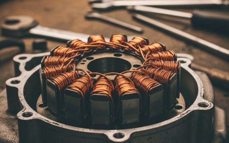
From the lamination side, tweaking Aw and Ac usually comes down to a few levers.
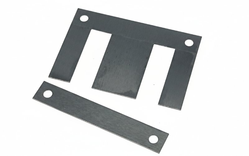
For laminated EI / UI stacks:
All three give magnetic headroom while keeping Aw almost the same.
On a lamination drawing this often shows up as new values for:
So when you negotiate a change with your lamination supplier, it’s useful to say explicitly which of these you’re willing to move, not just “I need 10% more Aw”.
This is the short, slightly rough guide we see work well in B2B projects.
Then compute the minimum Ap from your usual formula set or from the high-frequency or power-frequency guide you use.
Only then open lamination tables.
Write this bias into the spec. One line is enough:
“Prefer core-heavy / balanced / window-heavy solution for given Ap.”
It saves a lot of back-and-forth.
Once a tentative Aw is known:
Then sanity-check:
Adjust Aw or number of windows before changing anything in Ac.
Design calculations often assume a neat stacking factor. Real lamination stacks do not.
For each candidate lamination set:
If your “window-heavy” choice pushes Bmax too close to knee, either:
Doing this before the purchase order is a lot cheaper than asking for more stack height after tooling is made.
For high-frequency laminated or ferrite designs, the same Aw · Ac logic still holds, but the trade-offs shift.
Papers on solid-state transformers and matrix transformers show that at fixed Bmax and current density, transformer volume scales roughly with Ap / f, with volume minima when Aw and Ac grow in a certain proportion that balances copper and core volume.
In practice:
So even though formulas become more involved, the old question is still there:
“Given the Ap, do you want a bigger window and smaller core, or the other way round?”
You gain a lot by making that choice explicit early.
If you want your lamination supplier (or internal stamping shop) to hit the Aw / Ac compromise you had in mind, giving just Ap and stack height is not enough.
Include, at minimum:
Even these few extra lines stop your lamination stack from drifting back to the generic balanced point that may not fit your actual winding and insulation.
No. For a given Ap there is a family of Aw / Ac pairs that all satisfy the power equation. Which one is “best” depends on:
how expensive copper vs steel is in your business,
whether losses are dominated by core or copper,
insulation and clearance rules for your voltage level,
manufacturing limits on stack height and winding height.
So instead of searching for one magic ratio, pick a bias (core-heavy, balanced, window-heavy) that matches the project and then keep it consistent across that product line.
Stacking factor directly scales Ac. If you move from conventional Si-steel laminations (stacking factor around 0.95) to amorphous laminations (often near 0.8), the effective Ac drops while Aw stays fixed.
If you don’t adjust dimensions, your design quietly slides toward a window-heavy bias with higher Bmax. When switching material or coating, always re-calculate Ac with the new stacking factor and re-check whether you still like the Aw / Ac balance.
Only up to a point.
You can squeeze more copper into the same Aw by:
picking thinner enamel / insulation,
improving winding practice,
accepting hotter copper (higher J).
But Kw and Ku have physical limits. High-voltage designs especially need room for solid insulation and ducts, so Kw naturally drops as kV rating goes up.
If your computed Kw is already high and the sample coils are still cramped, it’s usually a sign that Aw itself needs to grow, not that the winding team should “try harder”.
Yes. Ferrite core catalogues also use Ap = Aw · Ac as a sizing metric and publish area products for each shape.
What changes is:
you operate at much higher frequency,
Bmax is lower,
current density and skin effect become more critical.
So high-frequency ferrite designs often live in window-biased territory, but the same principle holds: once you have Ap, you can still choose between more window or more core area. The right answer depends on losses and manufacturability, not on the material alone.
If you only have rating and voltages:
Use your standard design sheet or software to estimate: needed Ap
initial Bmax, J
approximate Kw based on voltage class.
Decide which problem hurts you more in this product: core loss and magnetizing current
or winding / insulation space.
Tell the supplier: the target Ap,
preferred bias (core-heavy / balanced / window-heavy),
minimum Aw you believe you need (from your Kw estimate).
This is enough for a lamination specialist to pick or tweak a stack that respects your intent instead of just matching kVA tables.