Let Sino's Lamination Stacks Empower Your Project!
To speed up your project, you can label Lamination Stacks with details such as tolerance, material, surface finish, whether or not oxidized insulation is required, quantity, and more.
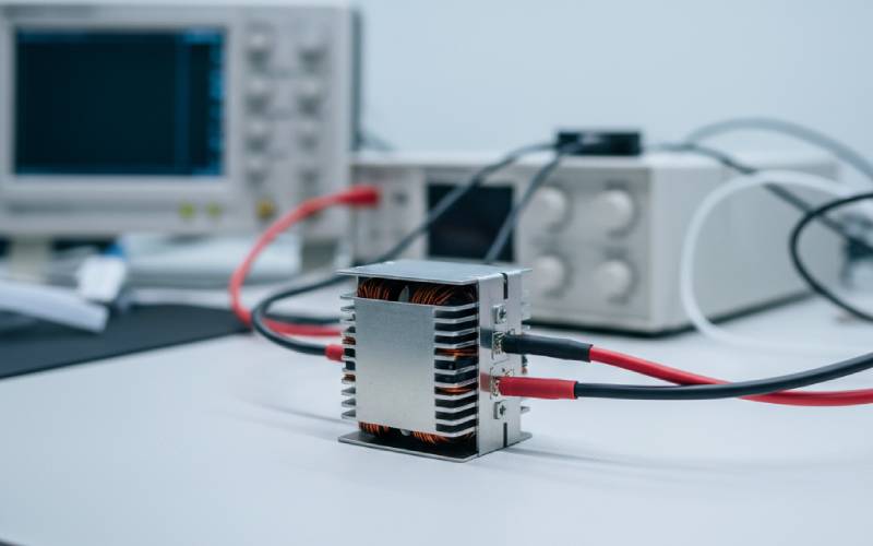
A transformer can look like a simple metal box. But on the inside, a smart way of putting it together makes it work. This process is called transformer design. A power transformer changes electrical voltage so it is higher or lower. This article will show you how to design a transformer. We will explain the hard parts in an easy-to-understand way. You will learn about the core, the windings, and how to make your transformer work well without wasting power. Reading this will help you see what makes a good transformer. It will also show you how an engineer makes one from the very beginning.
A power transformer is a piece of electrical equipment. It sends electrical power from one circuit to a different circuit. It is able to do this with no moving parts. The main job of a transformer is to change the amount of voltage and current. A transformer can be a step-up or a step-down transformer. A step-up transformer makes the voltage higher. A step-down transformer makes the voltage lower. This is a big help in many electrical systems.
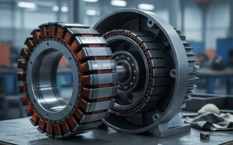
The transformer does its job by using a magnetic field. It has two main parts. One part is a magnetic core and the other part is a group of windings. There are at least two windings: the primary winding and the secondary winding. The primary winding takes in the input power. The secondary winding gives out the output power. When an input voltage is put on the primary winding, it makes a magnetic field that changes inside the core. This magnetic field, called magnetic flux, then makes a voltage in the secondary winding. The special thing about a transformer is seeing how all these parts do their job as a team. A simple transformer can do a lot of work.
A good plan for a transformer is very important for making one that is safe and does its job well. A transformer that is not designed well can cause big problems. It can get too hot, waste power, and even stop working all at once. An engineer has to think about a lot of things during the transformer design process. The main goal is to make a transformer that can handle the amount of power it’s supposed to. It also needs to work very well without wasting power. A transformer that works this well saves both money and power.
A good transformer design also makes sure the transformer will keep working for many years. It needs to be able to deal with the heat it makes from power loss. The insulation has to be strong enough for the highest voltage it will use. The way the parts are put together must be correct. A good transformer is one you can count on to work. For instance, a 100 kVA power transformer must be planned with care. This is to make sure it can handle that much power safely for a long time. An engineer’s job is to find the right mix of price, size, and how well it works in the final transformer design. This is what makes the transformer a helpful part in an electrical system.
To design a transformer, you have to know what you need it to do first. You need to figure out the basic details about the transformer. These details are the first step for all your math work. If you don’t have them, you cannot build a transformer that is useful.
Here are the important things to decide at the beginning:
After you have this information, you can start to figure out the other parts of the transformer with math. For example, the input power and output power help you find out how much current will move through the primary and secondary windings. These first steps are the base for your entire transformer design.
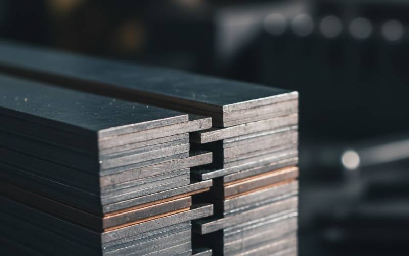
The magnetic core is like the heart of the transformer. Its job is to show the magnetic flux where to go. It guides it from the primary winding over to the secondary winding. The material used for the core is a big deal for how well the transformer works. Most transformer cores are made of a special material called silicon steel. This material lets a magnetic field pass through it very easily.
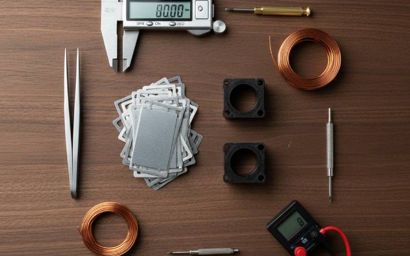
The core is not one solid piece of steel. It is built from many thin metal sheets. These sheets are called laminations. Each lamination has a very thin coat of insulation. This keeps it separate from the other sheets. This lamination setup is very important. It helps to lower the amount of power that gets wasted in the core. This wasted power is known as core losses. A solid core would let large electrical currents move inside it. This would create a lot of heat and waste a lot of power. The thin laminations stop these currents, which makes the transformer work a lot better.
The voltage of a transformer depends completely on the number of turns in its windings. The connection between the input voltage, the output voltage, and the number of turns is very simple. This connection is known as the turns ratio. If the secondary winding has more turns of wire than the primary winding, the transformer is a step-up transformer. If the secondary winding has fewer turns, it is a step-down transformer.
To figure out the number of turns, engineers use a formula. This formula is often called the transformer EMF equation. A more simple way to think about it is “volts per turn.” First, you figure out how much voltage one single turn of the winding can manage. For instance, if you find that the volts per turn is 0.5, and you need a primary winding for 120 volts, you would figure it out like this:
Number of turns = Winding Voltage / Volts per Turn Number of turns = 120 volt / 0.5 = 240 turns
You would need 240 turns for the primary coil. If you wanted a 12-volt secondary output, you would need 12 / 0.5 = 24 turns for the secondary winding. This math is a very important step when you design a transformer.
The winding of a transformer is a coil made of wire. This wire, or conductor, is almost always copper. Copper is a good pick because it carries electricity very well and doesn’t cost too much. The thickness, or gauge, of the copper wire you pick is a big deal. The right thickness depends on how much current the winding has to carry.
A winding that carries a lot of current must have a thick copper wire. A winding with only a little current can use a thinner wire. If you pick a wire that is too thin for the amount of current, it will get too hot. This heat can melt the wire’s insulation. This can cause the transformer to break. To find the right wire size, you first figure out the primary current and secondary current. You can do this using the transformer’s power rating (VA rating).
| Power Rating | Input Voltage | Primary Current | Suggested Wire |
|---|---|---|---|
| 100 VA | 120 Volt | 0.83 Amps | Thin |
| 1000 VA | 120 Volt | 8.3 Amps | Medium |
| 5000 VA | 120 Volt | 41.7 Amps | Thick |
This table shows a simple idea. As the current gets bigger, the wire needs to be thicker. Picking the correct conductor makes sure the transformer can manage the power it needs to supply without getting too hot. This is super important for a safe transformer that you can count on.
No transformer is perfect. Every single transformer has some wasted power. This wasted power turns into heat. There are two main kinds of losses in a transformer: core losses and copper losses. Knowing about these is very important when you design a transformer to work very well.
Core losses are losses that happen in the magnetic core of the transformer. They are caused by the magnetic field inside the silicon steel, which is always changing. These losses are there whenever the transformer is on. This is true even if nothing is connected to the secondary winding. Using thin laminations and a good material for the core helps keep these losses small.
Copper losses are losses that happen in the copper windings. They are caused by the resistance of the electrical wire. When current moves through the wire, it makes heat. This is also known as I²R loss. Copper losses get bigger as the transformer does more work. More current means more heat and more wasted power. A good transformer design will try to make both core losses and copper losses as small as possible. This is done to make the transformer work better and waste less power.
The way the primary and secondary windings are put on the core is called the winding arrangement. This setup can change the way the transformer does its job. The main goal is to get the best magnetic connection between the primary and secondary coils. This means you want as much of the magnetic flux from the primary winding to connect with the secondary winding as you can.
A normal setup is to wind the secondary coil right on top of the primary coil. There is a sheet of insulation between them. This setup puts the two windings very close to each other. Putting them close together helps to lower something called leakage flux. Leakage flux is a magnetic field that escapes and does not connect with both windings. A good winding arrangement makes the transformer’s voltage regulation better. Voltage regulation shows how much the output voltage goes down when the transformer is working at full power. A good setup helps it work better when the amount of power it gives out changes. It also affects the transformer’s impedance and its power to keep the input and output circuits separate.
All the wasted power in a transformer turns into heat. If this heat is not taken away, the transformer will get hotter and hotter. Too much heat can hurt the insulation. This can cause the transformer to break. Because of this, every power transformer must have a way to cool down. The cooling methods that are used depend on the size and power rating of the transformer.
For small transformers, just the air moving around it is enough to keep it cool. The heat travels from the core and windings to the outside surface, and then moves into the air. For bigger transformers, this is not good enough. A larger power transformer, like a 100 kVA unit, might have fins on its outside case. These fins give more space for the air to touch, which improves cooling. Very large transformers are often put inside a tank that is filled with a special oil. The oil soaks up the heat from the transformer core and windings. The hot oil then moves around and is cooled by air or by water. Picking a way to cool the transformer is a very important part of the transformer design.
After an engineer has finished planning the transformer and has built it, it needs to be tested. Testing is done to make sure the transformer does what it is supposed to do and is safe to use. There are a few normal tests for a transformer.
One test is called the open-circuit test. For this test, voltage is put on the primary side, but the secondary side is left open with nothing connected to it. This test checks the core losses of the transformer. Another test is the short-circuit test. The secondary output is connected with a thick wire, and a very small voltage is put on the primary side. This test checks the copper losses and the transformer’s impedance. At the end, a voltage regulation test is done. It checks how the secondary voltage changes when there is no load and when there is a full load. These tests make sure the transformer has the right voltage and works as well as you wanted. This is the last check for a transformer that was designed well.