Let Sino's Lamination Stacks Empower Your Project!
To speed up your project, you can label Lamination Stacks with details such as tolerance, material, surface finish, whether or not oxidized insulation is required, quantity, and more.
If you treat lamination design as a cost-neutral detail, you end up paying for it every hour the transformer is energized. Most of the no-load loss, a fair slice of the sound level, and a surprising amount of reliability are already locked in the moment you pick thickness, stacking factor, joint style and overlap. This text is about getting those decisions right the first time.
Core laminations are not cheap decoration. For small single-phase distribution transformers, core material alone can be around one-third of total material cost, and its losses dominate the lifetime owning cost.
A useful mental reset is simple: begin with the no-load loss target and the allowed sound level, then force the lamination choices to serve that, not the other way round.
For 5–50 kVA units, a sensitivity study on 144 designs compared three CRGO thicknesses (0.18, 0.23, 0.27 mm) and showed that 0.23 mm M3 sheet usually gave both the lowest bid price and the lowest total owning cost in roughly four out of five cases. That does not mean 0.23 mm is universally “best”; it means you only win by going thinner when the loss capitalization is genuinely high, or when regulations physically force you there.
So before touching CAD:
You agree on the capitalization factors for no-load and load losses. You translate those into an acceptable no-load loss window. Only then do you ask: “Which thickness and material lets me hit that window with some margin?”
If you skip that loop, lamination “optimization” quickly becomes guesswork.
Grain-oriented electrical steel (GOES) is still the workhorse for conventional distribution transformers. Typical grades at 50/60 Hz run comfortably at inductions up to around 1.7 T with acceptable loss and magnetizing current, provided the flux path stays mostly along the rolling direction.
Datasheets for modern GOES show lamination factors above 95% even for thin gauges. One example: at 50 psi stack pressure, 0.18 mm strip gives lamination factors around 95–96%, 0.23 mm around 95–96%, 0.27 mm around 96–97%, and 0.35 mm can touch 98%, depending on coating. That alone tells you something. Thicker sheet slightly increases stacking factor, but hurts eddy losses. Thinner sheet does the opposite. There is no free lunch, just a balance.
Amorphous ribbon is different again. Its material loss is much lower, but the stacking factor of wound cores is around 0.8 rather than 0.95+, and the usable induction is lower, roughly in the 1.3–1.4 T region for practical designs. You gain a huge drop in no-load watts, you give back extra copper and a larger core window.
A practical way to think about it:
For standard-efficiency distribution transformers where the utility is still focused on purchase price, CRGO around 0.23–0.27 mm is usually the sweet spot.
For higher-tier efficiency classes where the penalty on no-load loss is severe, moving to 0.18 mm CRGO or amorphous makes sense, but only if manufacturing can live with the lower stacking factor and more fragile material.
The key is to choose thickness only after you have numbers on lifetime loss cost versus extra steel and copper. Gut feel is not enough any more.

Stacking factor is not something that happens to your core. It is a number you should design around and then measure.
Formally, stacking factor is the ratio of effective magnetic cross-section to the gross stacked area. It drops because of insulation coating thickness, burrs, gaps, and misalignment. In practice, for silicon steel around 0.3–0.5 mm at power frequency, typical stacking factors are about 0.92–0.96, and well-built GOES stacks can exceed 0.95 even at thinner gauges. Amorphous cores live lower, often near 0.8.
Here is a compact table you can actually use when sizing:
| Nominal thickness (mm) | Core type / material | Typical measured lamination factor at ~50 psi | Safe design value for ks | Comment |
|---|---|---|---|---|
| 0.18 CRGO | High-grade GOES, S- or D-finish | 0.95–0.96 | 0.95 | Good for very low no-load loss if cutting/handling are tight. |
| 0.23 CRGO | M2/M3 GOES | 0.95–0.96 | 0.955 | Often optimal for 5–50 kVA units on cost and TOC. |
| 0.27 CRGO | M3/M4 GOES | 0.96–0.97 | 0.96 | Slightly better stacking; eddy losses somewhat higher. |
| 0.30–0.35 CRGO | Heavier gauges | 0.96–0.98 | 0.97 | For large power units or when manufacturing prefers robust sheet. |
| 0.025 amorphous ribbon | Amorphous metal distribution transformer | 0.75–0.85 (wound core) | 0.80 | No-load loss drops sharply, but window grows. |
The building factor is the other silent player. It captures how much extra loss comes from joints, air gaps, distortion, and residual stresses beyond what the catalog loss says. Papers on joint design and lamination selection consistently show that poor joints and assembly pressure can add several percent to core losses even when the steel itself is identical.
If you are designing software or spreadsheets, it is healthier to:
Use ks from a table like the one above instead of a single magic 0.97. Apply a building factor on loss, not on area, and tune it against measured no-load tests from your own factory.
That way the math mirrors reality instead of wishful thinking.
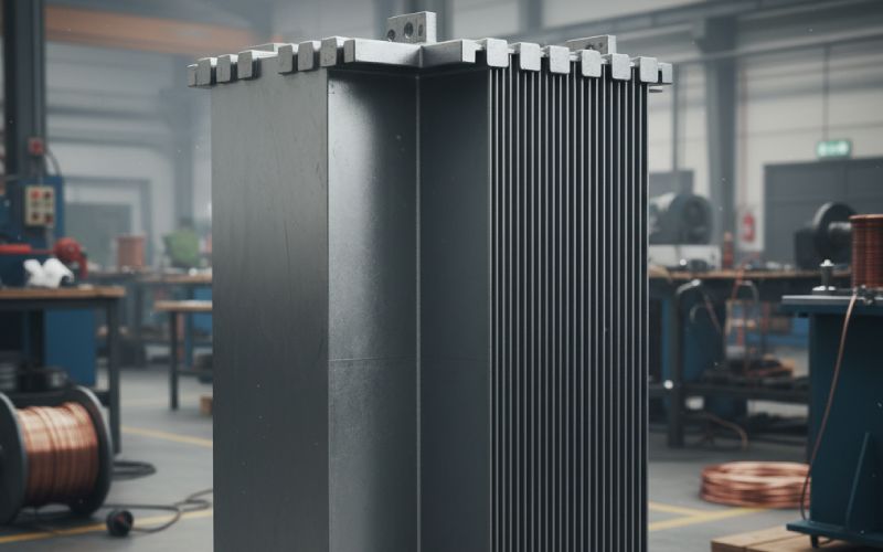
Most distribution transformers use stepped cores so the copper sees something close to a circular column, without you actually having to machine a circle out of solid steel.
Classic design handbooks give the fraction of the circle that is actually filled by steel for different numbers of steps. One widely used table shows around 85% fill for a three-step core, about 91% for five steps, roughly 93–94% for seven to nine steps, and around 96% for eleven steps.
The pattern is simple. The first few steps give a lot of improvement. After seven or nine, you are paying complexity for maybe one extra percent of circle fill.
For small pole-top units, three steps can work if the loss target is not aggressive and manufacturing wants simplicity, though many makers standardize on five. For 100–630 kVA class distribution transformers with tighter no-load specifications, five to seven steps are common. Nine or more steps start to make sense mainly for high-efficiency or larger units where every watt of loss is monetized and the winding geometry really benefits from a more accurate circle.
The other quiet variable is how you distribute step widths. For rectangular window designs, a pattern with narrower steps on the inside and wider on the outside tends to ease winding placement and give a more uniform current density without much penalty in flux distribution, provided the mean area is correct.
No universal rule here, but you can think in two passes. First pass: choose the number of steps from the rating and efficiency class. Second pass: adjust individual step widths so that the final circle seen by the winding is friendly to your conductor layout, not only to your finite-element model.
Joint design for laminations is where theory, FEA plots and production pressure all collide.
Butt-lap joints are simple to cut and stack. They also produce strong local flux crowding at the joints, higher magnetizing current and higher no-load loss. Slide decks from large transformer manufacturers still show this contrast clearly.
Fully mitred joints distribute flux better along the rolling direction, reducing local saturation. Step-lap mitred joints go further by staggering the cuts across several steps so the flux does not see a single abrupt discontinuity. Industrial data show that step-lap cores, compared to conventional butt-lap, can provide noticeable reductions in no-load watts, magnetizing current and sound level for the same steel grade and induction.
Today, for new distribution transformers above the very lowest ratings, mitred step-lap is basically the baseline. It is not exotic technology anymore. The interesting questions now are how many steps in the joint, what overlap length, and how you align the books.
There is a tempting idea that “more overlap must be safer.” The data disagree.
An experimental study varying the joint overlap length and the number of laminations per step in distribution transformer cores found that, within the practical range, the number of laminations per step had little net effect on loss, because manufacturing constraints trade it against other dimensions. However, increasing overlap from about 1 cm to 2 cm clearly increased core losses due to stronger flux distortion in the joint region.
What that means in practice:
Keep overlap as short as you can while still meeting mechanical strength and assembly constraints. Around 10 mm is often a reasonable starting point for mid-size distribution cores; going to 20 mm may cost you several watts for no real electrical gain.
Do not obsess over adding more laminations per step beyond what your cutting and stacking equipment can handle consistently. The study suggests that loss sensitivity to that parameter is low once the overlap and basic geometry are set.
More useful is to keep a strict tolerance on joint flatness and gap, and to control how the steps from one limb interleave with the yoke. That is where finite-element models actually do pay off, especially if you already have tooling and only small shape changes are possible.
Even perfect geometry on paper can be spoiled by sloppy cutting and stacking.
Insulation coatings and burrs eat into stacking factor, but burrs also introduce local mechanical stress and tiny gaps that worsen hysteresis and eddy losses beyond what the lamination catalog predicts. Standards such as ASTM A719 treat lamination factor as a function of sheet thickness, coating and compression, and they explicitly require deburring to get repeatable results.
Typical recommendations from both textbooks and mill data boil down to:
Keep burr height well below the insulation thickness, often quoted as under 10% of sheet thickness.
Control stack pressure during measurement and assembly; too low and gaps stay open, too high and you can distort the laminations or damage coatings, again hurting loss.
On the obvious side, but still surprisingly frequent in small shops: laminations with rust, bends or dents should be rejected, not “hidden” in the inner layers. Practical guides stress visual inspection and sorting for this reason.
If you want a quick health check on your process, a simple density-based stacking factor measurement on a compressed stack versus material density is cheap and revealing. A ks drifting down from 0.96 to 0.93 means you are throwing away cross-section and pushing flux density up everywhere, whether anyone changed the drawings or not.
GOES relies on carefully oriented grains. Mechanical working, tight bending, or punching close to edges all introduce stresses that degrade permeability and increase loss; stress-relief annealing can restore much of the magnetic performance, but only if the laminations are supported and heated in a way that preserves flatness and coating quality.
Typical stress-relief ranges for GOES are around 760–845 °C in a protective atmosphere such as dry nitrogen, sometimes with a controlled amount of hydrogen. The problem is that if core pieces are stacked or clamped in a way that differs from their final assembly condition, they can spring or warp after anneal. Then, when you actually build the core, small unwanted gaps appear in the joints and steps.
So lamination design and anneal practice need to talk to each other. If you move from butt-lap to multi-step-lap and from 0.27 mm to 0.18 mm sheet, but your anneal fixtures and pressure regime stay tuned for the old design, the theoretical loss savings will be partly eaten by distortion and coating damage.
This is one reason why some manufacturers buy fully assembled, stress-relieved multi-step-lap cores from specialized suppliers. Datasheets from those suppliers explicitly say that step-lap joints, when manufactured correctly, can achieve the lowest losses possible for a given steel grade in a flat-stack design.
If you keep core making in-house, it is worth running a short design-of-experiments exercise: vary anneal temperature, time and stack pressure for a fixed lamination design, and actually measure lamination factor and no-load loss on prototype cores. It is slower than changing nothing, but much faster than shipping noisy transformers for years.
Real cores need bolt holes, alignment slots and clamp interfaces. Every time you remove steel from a high-flux region, you force the flux to squeeze around the obstacle and raise local induction.
Transformer design texts point out that punched holes in yoke laminations, especially near the centre of the limb, distort the flux pattern and locally increase flux density and magnetostriction. That leads to extra core loss and sometimes an audible “hot spot” in sound measurements.
A couple of practical adjustments help:
Keep the highest-flux region of the yoke as clean as possible. Shift large holes slightly away from the centre line, or into zones where calculated induction is already lower because of step shape.
Synchronize the step-lap pattern with bolt locations so that bolts do not land where several steps already narrow the effective area.
When using offset yokes or reduced sections to save steel, re-check flux density with realistic stacking and building factors; many designs creep close to the knee of the B–H curve once those factors are applied.
These adjustments are not glamorous, but they are often the difference between a core that behaves like the FEM model and one that surprises you on the test floor.
Distribution transformers seldom see perfect sine waves. Non-linear loads and converter-rich grids inject harmonics that effectively raise the peak flux swing and increase dynamic losses in the core. Studies on transformer iron losses under distorted voltage show that higher harmonics can push no-load loss significantly above the value measured with a sinusoidal test, even when RMS voltage is kept the same.
Laminations interact with this reality in a few ways.
Thinner laminations reduce eddy current loss at higher harmonic frequencies, but, as seen earlier, may lower stacking factor slightly. A modest reduction in design induction, say from 1.7 T to 1.6 T, combined with slightly thinner sheet, can often keep harmonic-rich losses under control without excessive size growth.
On the other side, if you insist on high induction and thick sheet on a network known to have strong 3rd, 5th or 7th harmonics, the apparent core loss at site can overshoot your factory acceptance values by a noticeable margin. Customers may not blame laminations; they will just see an “inefficient transformer.”
Where load profiles are uncertain, a conservative rule is to keep some distance from the material’s rated induction, especially for amorphous cores whose magnetostriction is more sensitive, and to specify a test at a distorted waveform representative of the application when the contract is big enough to justify it.
Not a full design, just a snapshot to show how lamination decisions tie together.
Imagine a 250 kVA, 50 Hz, oil-immersed distribution transformer, three-phase, 11 kV / 0.4 kV, with a moderate efficiency requirement typical of many utilities.
You start with a no-load loss target of, say, around 450–500 W. The utility provides capitalization factors that make shaving 50 W of no-load loss worth some extra steel.
You consider 0.27 mm and 0.23 mm GOES. Catalog data and the sensitivity paper suggest 0.23 mm M3 is likely to give acceptable loss and a good balance of material cost for this rating. You aim for a design induction near 1.6 T under rated voltage, not at the absolute upper end.
Using the familiar volts-per-turn relation, you pick a volts/turn that gives a core cross-section around 0.036 m² at 1.6 T with 50 Hz. Gross area is then A_total ≈ A_net / ks. With ks chosen as 0.955 from the table, you get a gross area a few percent larger than the initial guess, enough to keep the steel honest.
For geometry, you select a five-step circular leg and yoke configuration. That gives about 91% circle fill, so the copper sees a fairly round column. You specify fully mitred step-lap joints with about 10 mm overlap and a standard book size of five laminations per step, compatible with your cutting line and inspired by typical multi step-lap core offerings.
You decide that bolt holes in the yoke should sit slightly off the highest-flux zone and align the step pattern so that bolts do not hit the narrowest effective sections.
Finally, you feed all this into your core-loss model with a realistic building factor, say 1.05 on catalog loss at the chosen induction, reflecting your factory’s historic performance on similar cores. If the predicted no-load loss is still too high, you know you must either drop induction, go thinner, or improve joint design and anneal practice; there is no point shaving a few turns and hoping.
On the shop floor, you confirm stacking factor using the density method on sample stacks, aiming to see ks in the expected 0.95–0.96 band. If it comes out low, you do not blame the equations; you debug cutting, coating and stacking.
The lamination decisions are now traceable, testable choices, not tribal knowledge.
Lamination design for distribution transformers is one of those topics that looks mundane until you start putting numbers beside each “small” decision. Thickness, stacking factor, number of steps, joint style, overlap length, anneal conditions, hole placement and harmonic environment all push and pull on the same two outcomes: no-load loss and sound.
The official standards and data sheets explain the materials. What tends to be missing is the quiet discipline of treating lamination parameters as true design variables. Once you do that, the rest of the transformer — windings, cooling, insulation — has a much easier job.