Let Sino's Lamination Stacks Empower Your Project!
To speed up your project, you can label Lamination Stacks with details such as tolerance, material, surface finish, whether or not oxidized insulation is required, quantity, and more.

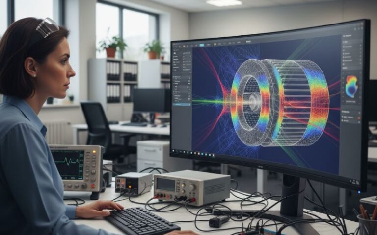
If your VNVH model gets stator slotting and rotor magnet forces even slightly wrong, the rest of the noise and vibration prediction chain will only look accurate on PowerPoint. The practical game is not to model everything, but to pick the right force orders and frames early and accept a few “good” approximations instead of a fake full model.
Over the last few years, most published work on electromagnetic NVH has converged around a similar storyline. Radial force on the stator teeth, shaped by stator slotting, dominates the electromagnetic contribution to noise. Structure and acoustics matter, of course, but they are usually treated as a response problem rather than the main source.
Several groups have shown that once you include the stator slot permeance function in your Maxwell stress calculation, the “problem” harmonics that match stator modes tend to come from a fairly small set of spatial orders, especially the low ones like 0, 2, 4, 6, depending on the slot–pole combination.
At the same time, rotor-side work has become more sophisticated. You see magnet-surface slotting to suppress high-order force components, rotor slit structures that deflect flux and trim torque ripple, and magnet-shape optimization designed to keep cogging torque and radial force away from structural resonances.
Most of these studies stop once they’ve shown a reduced force harmonic spectrum and a decent correlation to noise tests on one or two prototypes. That is helpful, but if you are trying to build a repeatable VNVH prediction process across a family of motors, you need to be slightly more systematic and, oddly, a bit more relaxed about perfection.
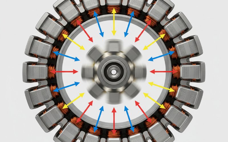
You already know the standard derivation. Radial air-gap flux density as the sum of PM and armature MMFs, modulated by a slot permeance waveform. Maxwell stress gives radial force density as roughly the square of that radial flux component divided by μ₀. The permeance is expanded into a series with terms at multiples of the slot number, and suddenly you have a forest of spatial–temporal force components.
In practice, what tends to matter for VNVH prediction is not the full expansion, but how carefully you keep track of three things.
First, which spatial orders will actually couple into the dominant stator modes. Many studies highlight that low spatial orders, especially 0th and a few low multiples related to the slot–pole combination, control most of the vibration and noise because the structural response falls off roughly with the fourth power of the order.
Second, the slotting model itself. There is a gap between the analytical relative-permeance model and what a 2D or 3D FEA with realistic tooth tips, chamfers, wedges, and saturation will produce. Analytical models are fast and convenient for parametric sweeps of slot pitch and width, but their force spectra start drifting once you move away from clean, uniform slots or push the design into deep saturation. That drift is usually small for torque, and noticeably larger for radial force.
Third, skew and fractional slotting. Skew is still often treated as a post-processing correction on the force harmonics. That can be fine if the skew is small and the structure is simple, but full VNVH prediction is sensitive to the exact spatial order distribution, and skew mixes them. If you are not careful, you end up “fixing” a cogging problem but accidentally strengthening a shell mode excitation.
The short version: use the analytical slotting model to understand trends, but lock in key designs with FEA that includes actual slot geometry and saturation, then freeze the relative permeability for harmonic extraction as done in some NVH-oriented PMSM work.
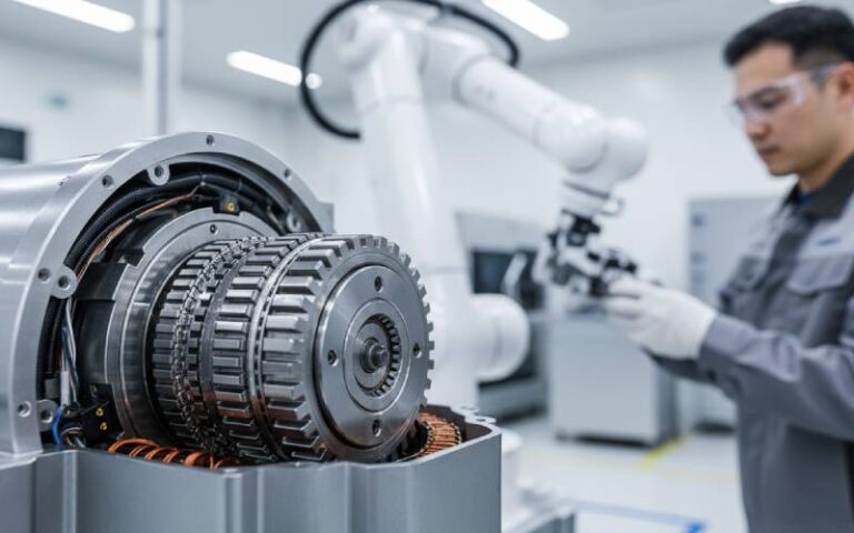
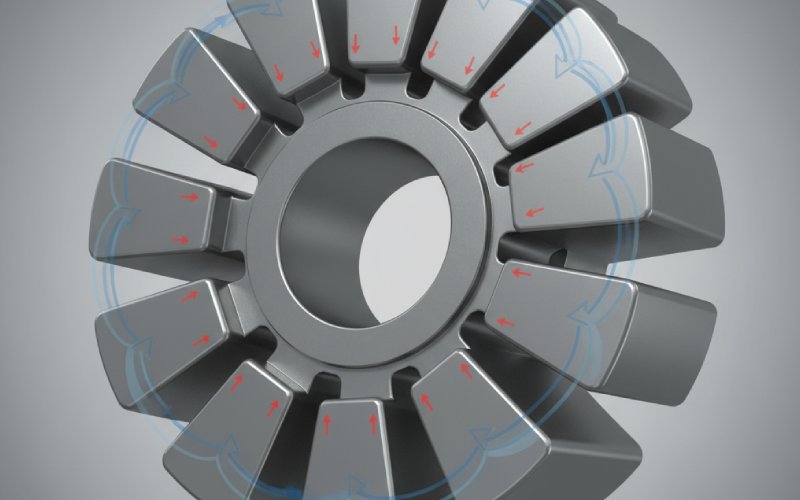
Rotor magnets bring their own set of force features. The usual suspects are cogging torque, torque ripple, and high-order radial force components from magnet edge effects and eddy currents. Cogging torque is often described as the torque that drives the rotor toward minimum magnetic reluctance as magnets sweep past the stator slots; the same reluctance variation produces time-varying radial forces that feed the NVH chain.
Recent work on magnet slotting approaches this from two angles. Some authors cut auxiliary slots directly into the magnet surface to modulate and weaken specific high-order radial force components without sacrificing average torque. Others introduce rotor slits or complex slot shapes (C/T/V type slits, step skewing) that increase reluctance along certain paths and shift the flux distribution.
The interesting part, from a prediction standpoint, is that magnet interventions often target orders that stator slotting alone would not have produced strongly. High-order radial forces can still contribute to noise by coupling through modulation effects and interacting with structural modes that are closer than you expected. Some studies explicitly show that high-order electromagnetic forces, once modulated by slotting, can generate vibration levels comparable to low-order sources.
If your model treats rotor magnet geometry as a minor detail and only adjusts PM thickness for torque and loss, you can easily miss these contributions. Then your noise prediction fails at a very specific load–speed point and nobody trusts the model anymore, even though it still computes torque just fine.
Rather than thinking “36 slots, 8 poles, that’s good” or “6-pole, 36-slot, watch order 6,” it helps to build a mental map that ties together slotting, magnet field orders, and the structural modes you care about. Several studies highlight how certain slot–pole pairs naturally create dominant force components at a small number of spatial orders and frequencies, which are then checked against the stator modal chart.
The table below is not a rigorous catalogue. It is more a compact way to keep your attention on the interaction that actually matters for VNVH prediction, using examples similar to those in recent literature.
| Example motor (PMSM) | Slot / pole pair | Dominant radial force spatial orders observed or reported | Typical excitation frequencies relative to electrical fundamental | Main geometric sources | VNVH risk pattern |
|---|---|---|---|---|---|
| Traction motor, ~6-pole, 36-slot | 36 / 6 | Strong 0th and 6th spatial orders in radial force; others smaller but present | Force components near multiples of fundamental and slot-passing frequencies | Stator slot permeance, interaction with PM and armature MMFs | Low-order forces align well with breathing and ovalization modes of stator, giving broad speed bands with high noise if not shifted |
| IPMSM, 12-pole, 36-slot | 36 / 12 | 0th, 6th, 12th orders noticeable; high-order sidebands from slot modulation | Rich spectrum around integer combinations of pole and slot frequencies | Concentrated windings, pronounced slot opening, interior magnets with saliency | Sensitive to specific speed ranges where 0th and 6th orders coincide with low radial modes; can suddenly “light up” narrow-speed bands |
| Surface PM motor, 12-slot / 14-pole with magnet slotting | 12 / 14 | High-order radial force components reduced by magnet slots; some redistributed | Modulated frequencies where high-order forces fold into lower apparent orders | Rotor magnet slotting pattern and depth, slot opening at stator | If optimization focuses only on high-order reduction, a few residual orders can still align with structural modes unless checked against modal data |
| High-voltage line-start PMSM with tailored slot combination | Various slot–pole sets | Distribution of force orders changes strongly with combination; some avoid low orders | Depending on combination, dominant forces shift up in order and frequency | Joint effect of stator slots and rotor configuration | Design can push main EM excitation away from structural resonances, but only if you treat structural modes as a first-class design constraint |
The key idea is simple: order charts are more useful than yet another static EM flux plot when you are aiming at VNVH prediction. Once you have the spatial orders and frequencies, you can project them onto your stator modes and see what is actually dangerous.
Most modern studies now run some sort of multi-physics chain: electromagnetic FEA to get radial force on stator teeth; structural FEA or an equivalent stator model to compute vibration; acoustic simulation or direct SPL measurement for final verification.
The nuance that often gets skipped in short papers but matters in real projects is how detailed each step needs to be relative to the others.
If your stator structural model is crude, spending days on high-fidelity EM detail is not efficient. Work on equivalent stator models has shown that getting the modal properties right, including the elusive 0th-order breathing mode, is fundamental for correct noise prediction. Some authors propose improved laminated-stack models precisely for this reason, demonstrating that naïve material properties can shift natural frequencies noticeably away from test values.
On the other hand, an excellent structural model cannot rescue a poor EM force model that averaged everything over slots. Studies that achieved close match between predicted and measured noise tend to put real effort into capturing non-uniform force distribution along the tooth surface, often mapping nodal forces into structural models rather than applying smeared ring loads.
So a workable rule emerges, not mathematically perfect but practical: match the level of detail in EM, structure, and acoustics so that none of them is obviously the weakest link. That sounds obvious, but look at your current workflow and it probably is not what you are doing.
Once the prediction chain is reasonably trustworthy, you can treat stator slotting and rotor magnet geometry as design variables in a structured optimization loop instead of one-off tricks.
Recent work has combined orthogonal experiments, nonparametric regression, and response surface modeling to relate design parameters such as slot dimensions, magnet layout, and winding configuration to radial force harmonics and NVH metrics. This kind of surrogate model allows you to scan many configurations quickly before validating a small set with full multi-physics simulation and test.
Rotor slit geometry studies sometimes categorize families such as “basic”, “C”, “T”, and “V” shapes, comparing magnetic field, torque ripple, and electromagnetic noise to identify the best compromise. These works often show that you can reduce radial force and associated noise by a noticeable margin while keeping torque and efficiency essentially unchanged, provided mechanical strength checks are passed.
On the magnet side, designs with auxiliary surface slots are tuned to flatten specific high-order force components responsible for narrowband whine. Simulations supported by tests have confirmed that targeted changes in magnet slot depth and pitch can significantly reduce noise without sacrificing output torque, as long as losses and thermal limits are respected.
The important point is that these interventions should be evaluated in the full VNVH context. A magnet slotting pattern that looks ideal from a radial force harmonic chart might interact badly with a real housing or mounting condition that shifts stator modes just enough to line up with a previously harmless order.
Putting this all together, a practical VNVH prediction flow focused on stator slotting and rotor magnet forces tends to look something like this, even if not everyone admits it in papers.
You start with a slot–pole and magnet layout that satisfies torque, efficiency, and basic manufacturing constraints. You then compute air-gap flux density and radial force using a model that includes stator slotting explicitly and represents the magnet geometry faithfully enough to capture local peaks and modulation effects. You map those forces into a structural model that has been checked against at least a few modal tests, especially for the lower circumferential orders and the breathing mode. Finally, you compare predicted vibration or SPL at key operating points with test data and adjust both models and designs.
Over time, as more projects pass through this loop, you accumulate a local pattern library: which slot–pole combinations tend to generate which orders, how rotor slotting really behaves in your manufacturing flow, which stator stack clamping schemes shift modes in which direction. That experience, more than any single sophisticated equation, is what makes your VNVH prediction credible.
The research record has already made one thing quite clear: electromagnetic NVH in permanent magnet machines is dominated by how stator slotting and rotor magnet forces interact in space and time, not just by their separate existence.
Once your models respect that interaction, even approximately, design decisions about slots and magnets stop being guesswork and start becoming controlled moves on a board you can actually see.