Let Sino's Lamination Stacks Empower Your Project!
To speed up your project, you can label Lamination Stacks with details such as tolerance, material, surface finish, whether or not oxidized insulation is required, quantity, and more.
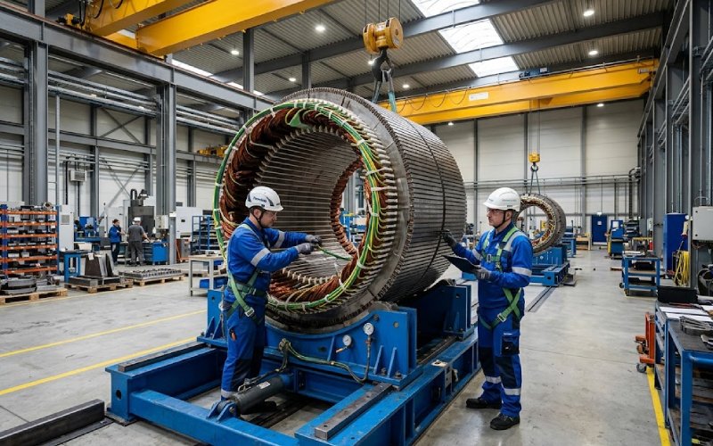
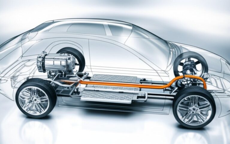
Large-diameter lamination stacks change the whole manufacturing logic of a wind turbine generator. At small and medium diameters, core building is mostly a stamping and stacking problem. At wind scale, not really. It becomes a combined problem of cut-edge quality, segment assembly, compression retention, housing stress, transport limits, and air-gap control. Once mean air-gap diameter moves into the multi-meter range, single-piece structures become less practical, segmented construction becomes common, and tolerance management starts deciding structural stiffness and load capacity.
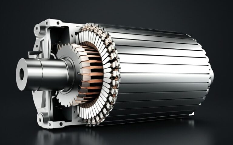
Direct-drive wind generators make this harder. Higher torque drives larger and heavier generator structures, and recent reviews point to manufacturing and assembly as primary scale-up bottlenecks, not just electromagnetic design. In this range, the stator core is no longer a passive magnetic part. It is part of the structural loop that protects the air gap.
The basic stack physics are familiar. Thin insulated sheets reduce eddy current loss. That part is settled. The manufacturing shift comes from scale.
For wind turbine stator cores, the stack has to survive:
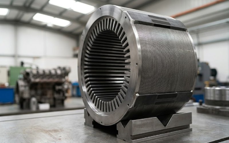
Published mechanical design work on direct-drive wind generators reports mean air-gap diameters in the 4–6 m range as typical for megawatt-class machines, with larger structures commonly moving to segmented construction because of manufacturability and transport limits. That is the threshold where lamination stack design starts behaving like a precision assembly system, not a sheet-metal subcomponent.
Punching still makes sense for production volume. But tool wear changes the edge condition over time, and the burr problem does not stay local. Review work on electrical steel manufacturing notes that increasing punch bluntness and burr formation reduce stacking factor and degrade downstream stack quality. At large diameter, repeated over many segments and many layers, a small edge defect becomes a system-level geometry problem.
The real issue is not burr height by itself. It is the chain reaction:
burr -> poorer nesting and stacking factor -> local compression inconsistency -> greater risk of interlaminar bridging or rubbing under load
That chain is where loss, heat, and long-term insulation damage start to meet each other.
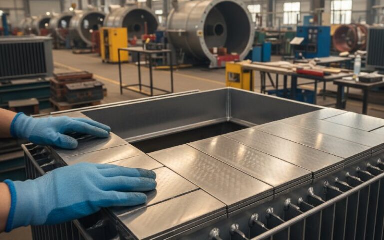
Segmented laminations are common because the full ring is often too large to stamp, move, fixture, or transport efficiently. They also help when the complete assembly weighs several tons. But segmentation introduces extra cut edges and parasitic air gaps between segments, both of which can alter machine performance.
A bad segment joint usually shows up in one of four ways:
None of these are abstract defects. They all move the air gap.
Joining is where many stator core builds get compromised.
Research reviews separate joining methods into two groups: methods built into the stack during lamination production, and methods applied after stacking, such as welding, clamping, and bonding. The target is always the same set of trade-offs: mechanical stability, low magnetic degradation, acceptable cost, high stacking factor, and production speed. You do not maximize all five. Not on a large-diameter wind core.
A detail that matters more than it gets credit for: to achieve the required stacking factor, the pack is typically pressed axially before welding. After release, the seam sees tensile stress. Once the core is mounted into the housing, radial stress and shear can develop because of geometric deviations and wall friction. Then service vibration and electromagnetic force add another load case on the seam. So a seam that looks fine on the bench may already be in the wrong stress state by the time the stator is fully assembled.
Interlocking is efficient and production-friendly. It fits stamping routes well. The drawback is that it locally disturbs the magnetic path and raises loss relative to an ideally insulated reference stack. Fatigue strength in the through-thickness direction is also weaker than a strong welded joint. For large wind generator laminations, interlocks can still work, but they need to be used with restraint. Too many retention points, wrong locations, or poor split-line planning will show up later as localized loss or looseness.
Welding delivers stronger retention. It also creates the most obvious risk of local electrical bridging, coating damage, residual stress, and heat-affected microstructural change. Comparative work shows laser welding generally produces a smaller heat-affected zone and lower residual stress than TIG-type welding, with better magnetic behavior as a result. That does not make welding “good” by default. It makes laser the less damaging version of a still intrusive operation.
Bonded stacks preserve insulation and remove many weld-related penalties. They are attractive from a magnetic and damping standpoint. The open issue is durability under temperature, cyclic loading, process cost, and scalability in heavy-duty applications. For very large wind turbine generator laminations, bonding is usually a selective answer, not a universal one.
This is one of the more useful directions for large-diameter stack manufacturing. Review data shows adaptive pulsed laser approaches can sharply reduce total energy input, in one reported case down to about 23% of the energy used by a traditional pulsed route. But there is a catch. Sheet thickness variation can reach up to 8%, which means gap sensing and real-time path control become necessary if the process is supposed to hit only the interfaces that need joining. Good process idea. Harder production problem.
| Manufacturing issue | What goes wrong in practice | What should be controlled first |
|---|---|---|
| Cut-edge quality | Burr growth, local insulation damage, reduced stacking factor | Tool wear window, burr limit by segment family, edge inspection frequency |
| Segment assembly | Split-line mismatch, parasitic gaps, local height variation | Segment datum strategy, pre-compression sequence, split-line metrology |
| Welding | Heat-affected zone, coating breakdown, interlaminar bridges | Seam position, heat input, restraint state during welding, post-weld loss checks |
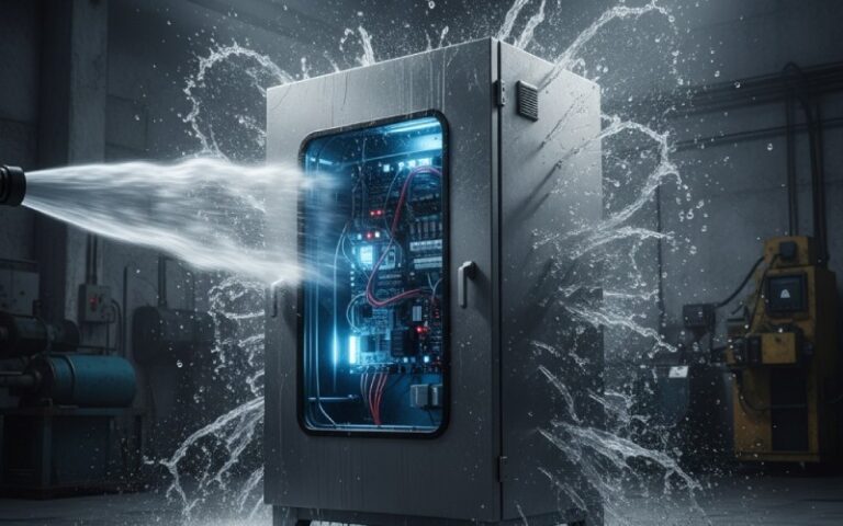
| Housing insertion | Radial stress, friction-induced shear, core ovality | Housing fit tolerance, insertion method, roundness check before and after seating |
| Transport and handling | Stack relaxation, re-indexing error, distortion after lifting | Lift point design, temporary retention method, requalification after each move |
| Final air-gap geometry | Eccentricity, local closure risk, uneven magnetic pull | Build-to-gap strategy, full-assembly metrology, compensation plan before winding closure |
This is the practical sequence. Not because it looks tidy. Because these are the places where large stator cores usually stop behaving like the CAD model.
For wind machines, especially direct-drive machines, air-gap behavior is not a downstream detail. Structural studies of direct-drive generators show that the air gap must remain small and uniform for proper torque transfer, and that non-uniformity increases sensitivity to magnetic force imbalance, bearing compliance, and structural deformation. In one line of analysis, acceptable eccentricity is treated as needing to remain within roughly ±10% of air-gap length. Beyond that, risk rises fast.
There is also an ugly trade. A larger design air gap gives more tolerance margin and can be structurally easier to live with. But it usually increases active material demand and cost. A smaller air gap helps electromagnetic performance, then asks for more stiffness, tighter assembly control, and better bearing behavior. So the lamination stack is stuck in the middle of that compromise. Again. It always is.
That is why a serious stator core manufacturing route should be planned backward from the final operating air-gap map. Not forward from the stamping die.
For large-diameter lamination stacks, the process route should be built around four locked checkpoints.
Do not treat burr as a cosmetic defect. Qualify cut-edge condition by segment family, not just by material lot or tool ID. Large segmented cores multiply edge count. The inspection logic should reflect that.
A lot of problems begin after the first “good” compression result. The stack is pressed. Welded or clamped. Released. Moved. Re-seated. Inserted. Measured again. Every one of those steps changes the stress state. If compression retention is not designed through the full route, the first acceptable reading means very little.
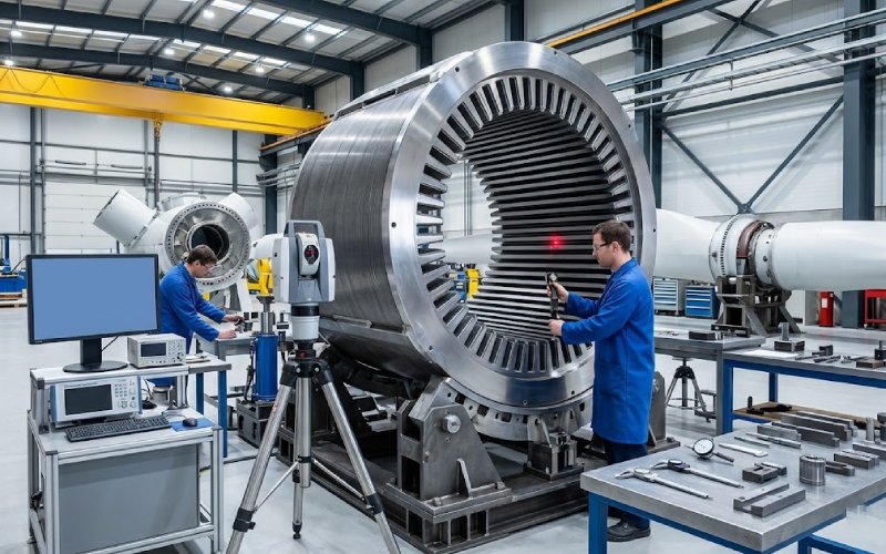
Final inspection is too late for a part this large. The useful checkpoints are:
That sequence matches where geometry tends to move.
For a wind turbine stator core, acceptable punch data, acceptable weld coupons, and acceptable housing dimensions do not automatically add up to an acceptable core. The integrated assembly state matters more. Air-gap protection sits there. Not in the individual certificates.
A workable release checklist usually needs these items:
That list is longer than most standard stack inspections. It should be. Wind turbine generator laminations are not forgiving once installed.
Because past a few meters of air-gap diameter, one-piece structures become much less practical to manufacture, transport, and assemble. Segmentation improves manufacturability and transportability, but it also increases the number of cut edges and interfaces that must be controlled.
Not automatically. Welding gives strong retention, but it can also damage coating, create interlaminar bridges, and increase residual stress. Laser-based welding generally performs better than TIG-type welding from a magnetic damage standpoint, but seam layout and heat input still decide the outcome.
Because burr reduces stacking factor, disturbs compression consistency, and raises the risk of local insulation breakdown or electrical bridging between laminations. On a segmented large-diameter core, that effect repeats many times.
Stress redistribution after joining and assembly. A core that looks acceptable right after pressing can shift after weld release, handling, or housing insertion. Radial stress, wall friction, and vibration loading all matter.
Partly. It gives more structural margin, but usually increases active material demand and cost. A larger air gap is a design trade, not a free correction for weak manufacturing control.
At minimum: roundness, local stack height, segment fit, compression retention, seam condition, and the final air-gap map in assembled state. If those are checked too late, the correction cost rises sharply.
If the application is a large wind generator, the useful supplier conversation is not “Can you make laminations?” Too broad.
The better questions are:
That is where project risk sits.
And where good lamination stack manufacturing starts to look different from ordinary motor core production.