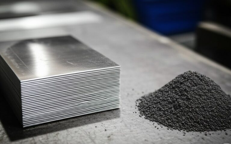
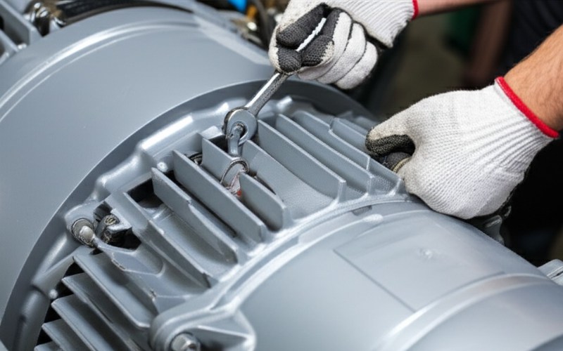
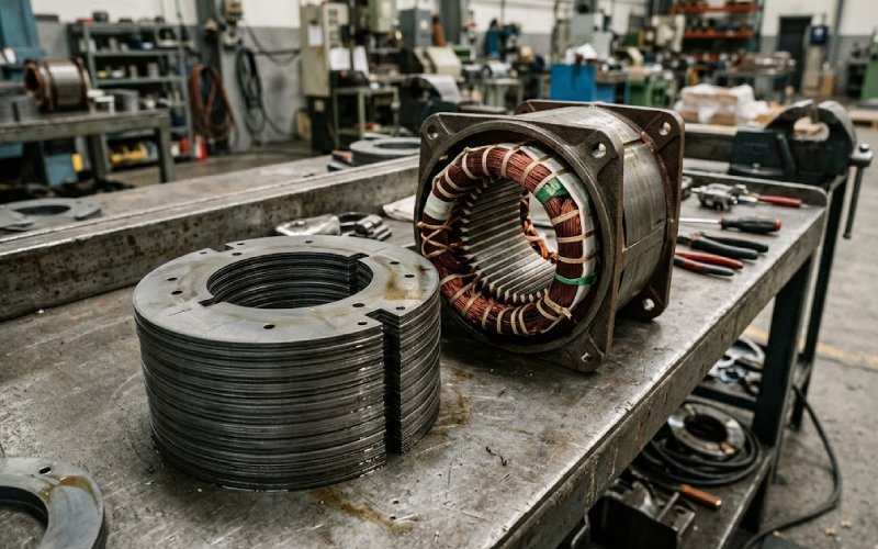
Let Sino's Lamination Stacks Empower Your Project!
To speed up your project, you can label Lamination Stacks with details such as tolerance, material, surface finish, whether or not oxidized insulation is required, quantity, and more.
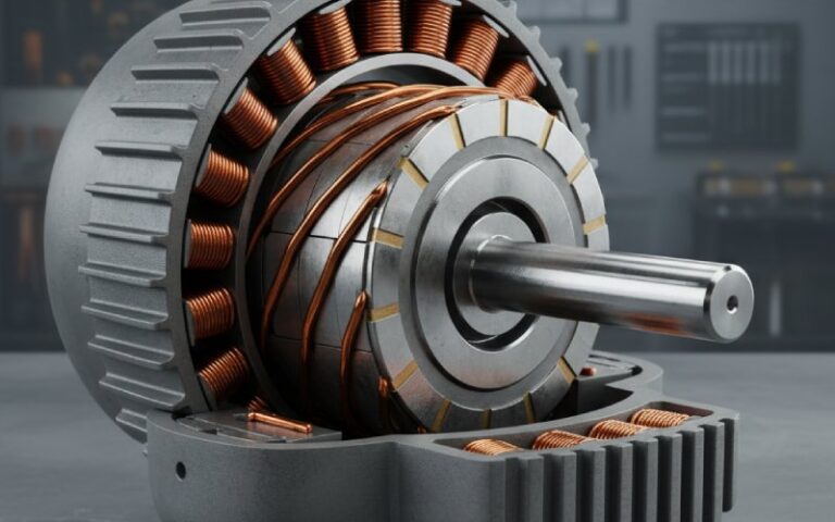
Compressor motor laminations usually lose life for boring reasons. Not steel grade alone. More often it is contamination in the oil circuit, a local hot spot that never shows up in average temperature data, or an insulation system that looked fine on paper and shifted after real chemical exposure and real manufacturing stress. In hermetic service, moisture and byproducts can push corrosion, copper plating, hydrolysis, sludge, and insulation damage long before the stack itself looks visibly damaged. Meanwhile, built-core losses can move away from sheet data once cutting, joining, stacking, and housing pressure enter the picture.
Oil gets blamed a lot. Too much, really.
Inside a compressor motor, the stack does not care about oil in some abstract sense. It cares about the chemistry around it. Water changes that chemistry fast. Acid formation changes it again. Polyester-based insulation can become brittle in the wrong moisture-lubricant environment, and once hydrolysis starts, the damage does not stay politely limited to one material layer. It spreads through the insulation system.
That matters for laminations because the stack is buried inside that insulation package. Slot liner stability, varnish condition, lead insulation, phase insulation, all of it changes thermal behavior. A core that was acceptable during bench validation can start running with less margin after chemical aging, even if the magnetic steel itself has not changed much. Not a dramatic failure at first. More like a quiet shift. Then
For sourcing and design, the practical rule is simple: qualify the lamination stack in the full motor environment, not as a dry standalone metal part.
Compressor motors are usually discussed with average winding rise, insulation class, and shell temperature. Useful. Not enough.
The weak point is the local hot spot. In rotating machine insulation work, the usual rule of thumb still holds: a 10°C increase in operating temperature cuts insulation life by about half. That is rough, yes, but still useful. And it gets more relevant in compressors because hot spots tend to be local, stubborn, and easy to hide inside average values.
The cooling path is part of the issue. In one compressor motor cooling study, only about 4.48% of the total suction gas moved through the motor-cooling path. That is a small share doing a large job. So when designers rely on bulk gas temperature or average thermal models, they can miss the section that is actually consuming insulation life. End turns, tooth tips, end packs, or a poorly washed segment of the stator can decide the outcome.
This is why a higher insulation class by itself does not solve much. If the hot spot is wrong, the class rating just delays the argument.
Interlaminar insulation is not a box to tick. It is a trade.
Thin coatings can help punchability and joining. Some coating systems are chosen because they behave well in welding or automatic stacking. Others are chosen because they hold electrical separation better after thermal exposure. Some offer better corrosion resistance. Some recover less well after later process heat. There is no “best” coating once you leave catalog language and enter compressor duty.
The wrong way to choose coating is to start with dielectric language only. The better route is to lock the manufacturing route first. Punching method. Burr target. Joining method. Any stress-relief heat treatment. Housing fit. Oil exposure. Then choose the coating system that still makes sense after those steps, not before.
That order matters more than people like to admit.
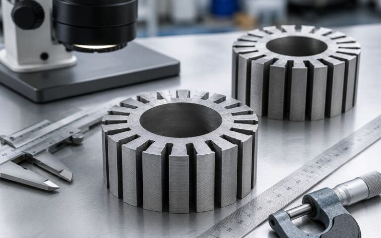
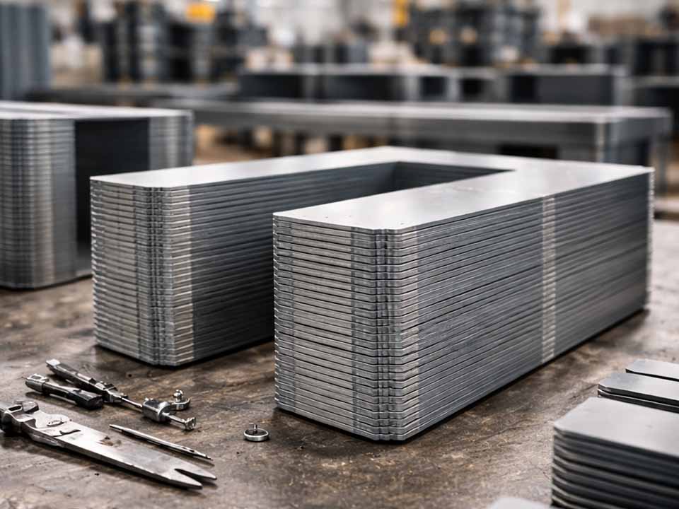
Built-core performance is where many lamination programs go off course.
Cutting introduces residual stress and local magnetic damage near the edge. Joining methods change loss again. Housing fit can add compression effects and, in bad cases, damage interlaminar separation. Review work on electrical steel manufacturing reports that cutting-related iron loss deterioration can vary by a factor of two or more, depending on geometry, material, and process details. It also reports cases where punching and interlocking produced much higher average core loss than laser-cut and bonded stacks. So the incoming sheet is not the final magnetic product. Not even close.
For compressor motors, that gap matters more because the thermal environment is already tight. Any avoidable core loss turns directly into heat inside a system that may have limited motor cooling flow and chemically stressed insulation.
Use this as a design and sourcing table. It is blunt on purpose.
| Risk Area | What Usually Goes Wrong | What to Specify or Review |
|---|---|---|
| Oil exposure | The fluid is treated as a lubricant only, not a chemical carrier | Validate materials against oil, refrigerant, moisture, and aged-fluid conditions |
| Moisture control | The motor is dried, but the lubricant or buried insulation retains water | Define drying method, drier strategy, handling limits, and contamination checks |
| Thermal design | Average temperature looks acceptable while one region runs hot | Review hot-spot margin, local cooling path, and end-region thermal behavior |
| Lamination coating | Coating is selected for insulation value only | Match coating to punching, joining, thermal exposure, and corrosion demands |
| Burr control | Burr height is accepted as a cosmetic issue | Set burr limits and inspect for sheet-to-sheet contact risk |
| Stack joining | Interlock or weld choice is made for assembly convenience | Review magnetic loss shift, distortion, and local heating risk after joining |
| Housing fit | Pressing or shrink fit is treated as a neutral assembly step | Check insulation damage, stress effect, and stack loss after housing insertion |
| Core validation | Sheet certificate is used as final proof | Measure built-core loss after real manufacturing steps, not before |
These checks follow the actual failure chain: contamination, local heating, insulation aging, then magnetic and thermal drift inside the built core.
Most failures do not start with the lamination steel by itself. They start with moisture, chemical contamination, hot spots, and insulation-system aging. The lamination stack then runs with less electrical and thermal margin than the design assumed.
Moisture can drive corrosion, copper plating, hydrolysis, sludge formation, and insulation embrittlement. In the wrong lubricant-material combination, it can shorten insulation life well before visible motor damage appears.
No. It helps only if the real hot spot stays inside the available margin. Compressor motors often have uneven cooling, and small flow-path changes can move the hottest region enough to erase the extra class margin.
Start with the process route. Punching, stacking, joining, possible heat treatment, corrosion exposure, and oil contact should be reviewed first. Then choose the coating system that still holds electrical separation and manufacturability after those steps.
Because the built core is not the same as the incoming sheet. Cutting stress, joining method, housing fit, and local insulation damage can all raise core loss after the steel enters production.
Requalify the insulation system, not just the fluid properties. Review slot insulation, wire enamel, varnish, sleeves, tie materials, and the lamination stack’s thermal margin under the new chemical environment.
We build compressor motor laminations for applications where oil carryover, thermal concentration, and insulation reliability cannot be treated as side issues.
If your project has tight thermal limits, hermetic duty, or aggressive life targets, send the drawing and operating conditions first. We can review:
A drawing review early in the lamination stage usually costs less than correcting heat, loss, or insulation problems after stator validation.