Let Sino's Lamination Stacks Empower Your Project!
To speed up your project, you can label Lamination Stacks with details such as tolerance, material, surface finish, whether or not oxidized insulation is required, quantity, and more.
Rotor laminations rarely fail in a dramatic way at the beginning.
What usually happens is slower than that.
A motor starts running hotter than expected. Current drifts. Noise grows. A batch that looked acceptable during inspection becomes unstable in service. Then the investigation starts at bearings, shafts, cage casting, balancing, assembly. Sometimes that is fair. Often it is late.
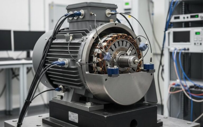
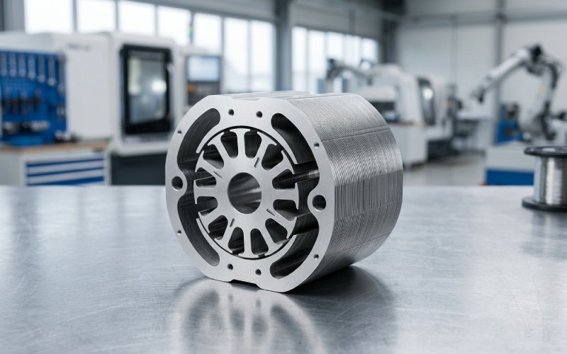
In our factory, rotor lamination stacks are not treated as simple punched steel parts. They sit at the center of magnetic loss, mechanical integrity, cage support, and air-gap stability. If the stack is weak, the rest of the rotor pays for it.
This article focuses on the failure points that matter most in induction motor rotor laminations, and the process controls we use to keep those risks from reaching production.
Most rotor stack issues do not begin as “material problems.” They begin as interface problems.
That is where trouble accumulates.
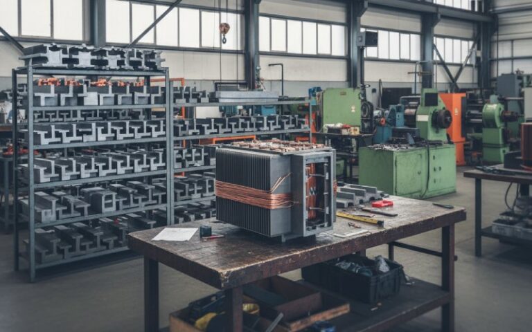
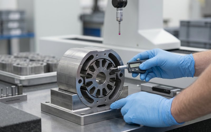
A rotor lamination stack may pass dimensional inspection and still create losses, vibration, or reliability problems later. That is why serious buyers do not only ask for material grade or stack height. They ask how the stack is made, joined, verified, and assembled into the rotor.
We do the same.
For rotor laminations, the cut edge is not a cosmetic detail. It affects magnetic behavior, coating survival, burr formation, and the chance of interlaminar contact.
A poor edge usually brings three things at once:
That combination is expensive. Not immediately, maybe. Later.
In our production, cut-edge quality is controlled through die condition management, burr monitoring, and process checks tied to lot release. We do not treat stamping as a step that ends when the shape looks correct.
Insulation between laminations only matters when it fails. Then it matters a lot.
Once insulation is damaged by burrs, compression, heat, handling, or joining, local conductive bridges can form inside the stack. That creates extra eddy-current paths. Then heat rises in places the drawing never warned about.
We control this by protecting coating integrity through stamping, stacking, and post-stack handling. For critical projects, we also recommend verification methods that go beyond dimensional checks, because the dangerous defect here is often hidden.
Rotor laminations do not need much geometric drift to create air-gap problems. Small misalignment inside the stack can amplify later during shaft fit, cage formation, and balancing.
Then the field complaint comes back as:
In practice, concentricity is not just a machining topic. It starts at the stack.
Interlocking, bonding, welding, clamping. All can hold a stack together. That does not mean they create the same stack.
Some joining methods improve throughput but introduce local stress or electrical bridging. Others preserve magnetic performance better but require tighter process discipline.
We choose joining routes according to motor design, stack geometry, downstream rotor process, and reliability target. Mechanical fixation alone is not our acceptance standard. The stack must also remain electrically and magnetically stable after assembly.
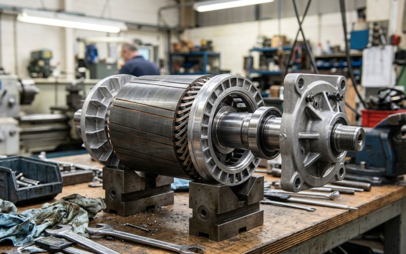
Rotor slots are where the lamination stack starts handing off responsibility to the cage. If the slot profile drifts, if local burrs rise, if the stack compresses unevenly, then bar insertion or casting quality starts to move with it.
The result is not always obvious at first. Sometimes it appears later as bar stress, uneven current sharing, or ring-junction fatigue.
So yes, slot geometry is a lamination issue. Not only a rotor cage issue.
Rotor skew helps control harmonic effects, torque ripple, and noise. But only when the skew is real in production, not only in theory.
Poor skew registration from lamination to lamination can leave the rotor with partial or inconsistent skew effect. That produces a motor that is difficult to explain on paper because the nominal design looks fine.
We pay close attention to skew consistency during stack formation, because the benefit disappears quickly once alignment discipline is lost.
Below is the condensed shop-floor version. No abstraction. Just the failure points that most often create real cost.
| Failure Point | What It Usually Causes | What Commonly Starts It | How We Control It in Production |
|---|---|---|---|
| Interlaminar shorting | Heat rise, loss increase, unstable efficiency | Burrs, crushed coating, local conductive bridges, joining damage | Burr control, coating protection, controlled stacking pressure, insulation-focused inspection |
| Cut-edge magnetic degradation | Higher no-load current, inconsistent motor performance | Worn tooling, excessive deformation, edge damage during punching | Die maintenance discipline, edge-condition monitoring, process correction before batch drift spreads |
| Stack eccentricity or poor concentricity | Vibration, directional noise, air-gap instability | Misalignment during stacking, poor fit control, tolerance accumulation | Stack alignment control, concentricity checks, fit discipline before rotor completion |
| Loose stack or unstable joining zone | Noise growth over time, fretting, dimensional drift | Weak bonding, unsuitable weld pattern, insufficient fixation | Joining method matched to design, fixation verification, stack integrity review before assembly |
| Slot profile damage | Bar stress, insertion issues, casting instability | Burrs, slot distortion, compression damage, tool wear | Slot-profile inspection, controlled tooling condition, handling control between stamping and stacking |
| Bar-to-end-ring stress concentration linked to stack condition | Crack initiation, torque irregularity, early rotor failure | Poor slot consistency, thermal cycling, uneven support from stack | Stable slot geometry, stack rigidity control, rotor build review at the interface stage |
This is one of the most expensive quiet defects in rotor laminations.
A stack can still look acceptable. Height is fine. Outer diameter is fine. Faces are acceptable. But if local insulation damage creates conductive paths between laminations, the rotor core starts carrying loss it was never supposed to carry.
The motor may not fail immediately. That is exactly the problem.
In our factory, we work backward from that risk. We do not ask only whether the laminations were stamped correctly. We ask:
That is how interlaminar faults are actually prevented.
A rough edge does more than create burr. It also changes the local state of the steel. Stress rises. Magnetic behavior shifts. Coating survival becomes less predictable.
This is why two stacks made from the same nominal material can behave differently in the motor.
Our approach is simple. We do not separate tooling condition from motor performance. If the die condition starts moving, the motor result will move later. So we track the cutting process as a performance variable, not only as a maintenance issue.
When buyers report rotor-related noise, they often start with balancing data. Fair. But many cases start earlier than balance correction.
Stack misalignment, poor concentricity, or unstable shaft relationship can distort the air gap enough to create vibration and acoustic issues that seem disproportionate to the measured error.
That is why we treat concentricity as a stack-level quality point, not a final assembly afterthought.
A stack that is mechanically weak does not always fail during production. It may pass through assembly, pass a routine check, then start moving microscopically in service.
The symptoms are messy:
We avoid this by matching the joining method to the motor duty and rotor design, instead of defaulting to the fastest fixation route.
Once slot geometry drifts, the cage starts inheriting the problem.
Bar fit changes. Local stress rises. Thermal behavior becomes less uniform. Then the weak point often shows up at the bar-to-end-ring junction, which is already one of the most stressed locations in many induction motor rotors.
For buyers, this matters for one reason: some rotor failures that look like cage failures are partly stack-discipline failures from much earlier in the process.
A serious supplier should be able to answer these questions clearly.
Not just stamping capability. Ask how they monitor burr height, how they manage die wear, and what action they take before edge degradation affects the batch.
Ask how coating integrity is protected during stacking and joining. If the answer stays general, that is usually a warning.
Not only after shaft assembly. Misalignment that starts early is harder to fix later.
If the answer is only about holding force or speed, the review is incomplete. Joining affects magnetic behavior too.
Rotor laminations can be dimensionally acceptable and still create heat, noise, or efficiency drift. A capable manufacturer knows this already.
When we build rotor lamination stacks for industrial motor applications, the target is not only “meeting the drawing.”
The target is this:
That is the difference between a punched part and a production-grade motor core.
If your current rotor stack issues include heat rise, vibration, noise, efficiency drift, or repeated rework during assembly, the lamination stack deserves a closer review than it usually gets.
Before mass production, we recommend reviewing these points:
| Check Item | Why It Matters |
|---|---|
| Burr level consistency | Reduces insulation damage and interlaminar contact risk |
| Coating condition after stamping and stacking | Helps preserve separation between laminations |
| Stack alignment and concentricity | Supports air-gap stability and lowers vibration risk |
| Slot profile consistency | Protects bar fit, casting quality, and cage stress distribution |
| Joining-zone condition | Reduces looseness, local stress, and long-term instability |
| Fit relationship to shaft and downstream rotor process | Prevents later distortion that can undo a good stack |
If you are sourcing induction motor rotor laminations and want to reduce heat, noise, or assembly rejection risk, send us your drawing or sample requirement.
Our engineering team can review:
That review is usually where avoidable failure starts to show itself.
Interlaminar shorting is one of the most common hidden defects. It often starts with burrs, damaged coating, or local compression damage inside the stack. The stack may still look acceptable from a dimensional standpoint, which is why the defect is often missed until heat or loss becomes visible in motor testing or field use.
Because dimensional inspection does not fully describe magnetic or electrical behavior. A rotor stack can meet drawing tolerances and still suffer from edge damage, insulation breakdown, local stress, or alignment issues that later create heat rise, noise, vibration, or efficiency drift.
Burrs increase the chance of insulation damage between laminations. Once conductive contact forms between sheets, local losses rise and hot spots can develop inside the rotor core. Burrs can also disturb slot quality and create downstream issues for rotor bar fit or casting stability.
Yes. The joining method affects more than mechanical fixation. It can introduce local stress, change interlaminar electrical behavior, and influence long-term stability of the stack in service. A joining method should be selected according to the motor design and duty, not only production speed.
The common causes are stack eccentricity, poor concentricity, weak stack fixation, and dimensional instability that affects the air gap after rotor assembly. In many cases, the vibration complaint appears during final motor testing, but the root cause started much earlier in the lamination process.
Buyers should ask how burr is controlled, how insulation integrity is protected, how stack alignment is verified, what joining method is used, and what checks are performed beyond basic dimensions. A qualified supplier should be able to explain these points clearly and connect them to production stability.
Induction motor rotor laminations do not usually fail because the concept was wrong.
They fail because the production controls around the stack were not tight enough.
That is where we focus our work. At the places where a motor drawing stops helping, and manufacturing discipline starts deciding the result.