Let Sino's Lamination Stacks Empower Your Project!
To speed up your project, you can label Lamination Stacks with details such as tolerance, material, surface finish, whether or not oxidized insulation is required, quantity, and more.
Lamination stacks decide whether a traction motor stays quiet near landing, stays efficient under repeated starts, and keeps enough margin when load and temperature drift away from the neat point used in simulation.
That is the real issue.
In a gearless elevator motor, low-speed smoothness matters more than in many other machines. A design can look stable at rated operation and still sound rough during creeping speed. It can pass average efficiency checks and still run local hot spots inside the stack. It can show acceptable torque and still lose headroom in the tooth tip or back iron.
So the lamination stack is not just a magnetic path. It is a loss map. A stiffness path. A tolerance amplifier.
And sometimes, it is the first place the motor starts to go wrong.
For traction motor noise, the usual discussion starts with control strategy. That is incomplete.
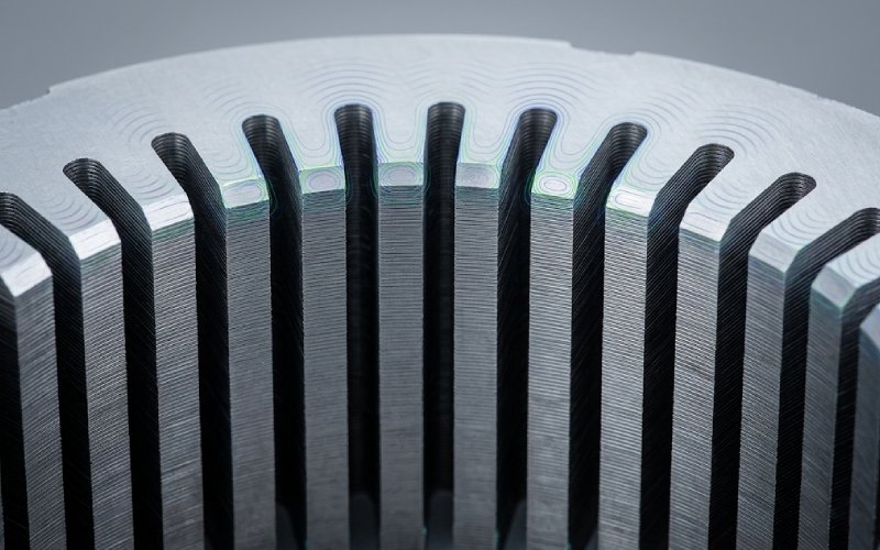
The lamination stack shapes the force pattern that the housing later turns into sound. Slot opening, tooth tip shape, yoke thickness, skew, stack rigidity, and local magnetic asymmetry all change the radial force picture. Small geometry changes can move a motor from smooth to rough, especially at low speed.
That matters in elevator duty because low-speed torque ripple does not hide easily. The machine has to feel stable near landing. No hesitation. No low-order roughness. No faint growl that appears only under light load and then disappears during full-speed travel.
Typical stack-related noise drivers include:
Some of these look minor during design review. Then the prototype arrives and the stator tells a different story.
Raw steel data is only the start.
Once laminations are punched, stacked, bonded, welded, riveted, or pressed into the housing, the core is no longer the material shown on the datasheet. Magnetic permeability shifts. Local loss rises. Stress builds around the cut edge and around joining points. Interlaminar insulation can degrade in ways that barely show up in a simple dimensional inspection.
That is why stator core manufacturing sits right in the middle of iron loss reduction.
Thin laminations help reduce eddy current loss. Yes. But that gain is not automatic. Thinner material is also less forgiving during handling and joining. If the stack process damages coating integrity or increases interlayer contact, part of the theoretical gain disappears inside the assembled core.
The same applies to stacking factor. Chasing a higher stacking factor looks attractive on paper. In practice, if that comes with coating damage, burr contact, or unstable compression, the motor may gain metal and lose margin.
This is where many reviews go soft. They compare designs using clean electromagnetic inputs, then treat the stack build as a secondary production step. It is not secondary. It changes the machine.
Safety margin in a lamination stack usually fades in three places.
This is often lost first at the tooth tip, slot bridge, or a thin back-iron section.
A motor may still produce target torque, but local saturation starts to crowd flux into places that raise loss and radial force. Once that happens, efficiency and NVH start moving together. Badly.
This one is quieter.
Small interlaminar faults, burr-driven contact, or stress-heavy joining zones can create local circulating currents and concentrated heating. Average efficiency might still look reasonable. The local thermal map will not.
And the local map is the one that matters.
The stack is also a structural part. If compression is uneven, if joining changes stiffness locally, if the built stator modes land near dominant electromagnetic force orders, the motor can become more vibration-sensitive than the model predicted.
So safety margin is not only about overload current or temperature class. It is also about whether the built lamination stack still behaves like the design intended.
| Lamination stack choice | Noise impact | Efficiency impact | Safety margin impact | What usually gets missed |
|---|---|---|---|---|
| Thinner laminations | Helps indirectly; does not remove force-wave problems by itself | Reduces eddy current loss | Can lower thermal load, but process sensitivity rises | Teams expect thin gauge to fix NVH |
| Higher stacking factor | Usually small direct effect unless stiffness or saturation shifts | Improves magnetic metal content | Helps only if insulation integrity survives assembly | Coating damage gets ignored |
| Aggressive interlocks, welds, or local joining | Can shift vibration behavior and create local asymmetry | Can increase core loss through stress or interlayer contact | May create local hot spots and weaker thermal reserve | Only average efficiency is checked |
| Better burr control | Reduces flux-path distortion and local asymmetry | Preserves core efficiency | Lowers risk of interlaminar shorting | Burrs are treated as cosmetic |
| Tooth tip and slot opening optimization | Often one of the fastest NVH gains | Can reduce local saturation and iron loss | Restores overload headroom in critical regions | Torque density is optimized first |
| Skew or step-skew | Often useful for low-speed smoothness | Usually a trade, not a free gain | Can improve force-order behavior, but may cost torque or back-EMF | Skew is chosen by habit, not by force spectrum |
| Better stack compression and rigidity control | Reduces mechanical amplification of electromagnetic forces | Usually indirect | Improves structural consistency and repeatability | The built core is assumed rigid enough without proof |
A release decision should be based on the built core, not only on simulation or raw material data.
At minimum, check these points:
If those checks are weak, the stack is not mature. Even if the CAD model looks clean.
Most useful fixes are not exotic. They are usually process discipline plus a few geometry decisions made early enough.
Focus first on tooth tip, slot opening, slot bridge, and yoke thickness. Those areas decide a surprising amount of the motor’s noise and saturation behavior.
Punch condition, tool wear, burr growth, and coating damage change the magnetic result faster than many teams expect. Edge quality is not a cosmetic issue.
A stack that works only in simulation is unfinished work. Lamination layout, joining method, compression method, and housing fit should be reviewed as one system.
Skew can help low-speed smoothness and reduce cogging-related roughness. It can also cost torque, complicate production, and shift back-EMF behavior. Use it deliberately.
The dangerous stack is often not the one with the worst average efficiency. It is the one with a hidden local fault.
If your application is a gearless elevator motor, the supplier should be able to answer these questions without drifting into sales language:
How do you control burr growth over tool life?
One good sample means very little. Stable burr control across production life matters much more.
How do you protect interlaminar insulation during stacking and joining?
A high stacking factor is not impressive if coating integrity is lost in the process.
How do you verify the as-built core, not just the incoming steel?
The useful answer includes production-stage validation, not only raw material certificates.
How do you manage cut-edge damage in narrow teeth and high-flux regions?
This is one of the easiest ways to lose efficiency and local headroom without noticing early enough.
How do you control stack rigidity and dimensional repeatability?
A loose or uneven stack can turn an acceptable electromagnetic design into an NVH problem.
A serious lamination supplier should be strong in all five areas. Not one. All five.
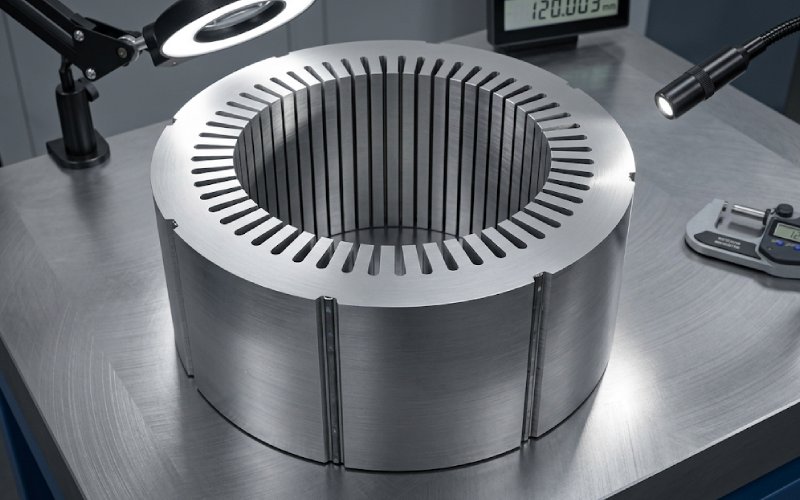
Lamination stacks form the stator or rotor core, but their role goes beyond flux guidance. In elevator traction motors, they directly affect motor noise, core efficiency, thermal behavior, and safety margin, especially at low speed and repeated-start duty.
Because low-speed smoothness depends heavily on radial magnetic force, torque ripple, and structural response. Lamination geometry, skew, tooth shape, stack rigidity, and local magnetic asymmetry all affect how much vibration the motor generates and how much the housing amplifies.
Stator core manufacturing changes the magnetic material after the design stage. Punching, burrs, joining stress, coating damage, and interlaminar contact can all raise iron loss and reduce real efficiency in the built motor.
Not always.
Thinner laminations usually help iron loss reduction, but they also raise process sensitivity. If stacking, joining, or insulation control is weak, the expected efficiency gain can shrink fast.
Usually not one dramatic failure. More often it is gradual loss of margin through local saturation, interlaminar faults, hidden hot spots, or vibration sensitivity in the assembled stator.
Start with the stack features that shape reluctance variation and local saturation: tooth tip, slot opening, slot bridge, yoke thickness, skew choice, and built-core rigidity. For NVH optimization, those usually matter earlier than cosmetic housing changes.
Ask about burr control, insulation protection, joining method, as-built core validation, and low-speed consistency. If the supplier only talks about material grade and punching accuracy, the picture is incomplete.
A lamination stack does not fail only when it cracks, shorts, or overheats.
It also fails when it makes the motor louder than expected. When it pushes loss above plan. When it removes the small reserve that should still be there after production tolerances, assembly stress, and operating drift have done their work.
That is the real standard for elevator traction motor laminations.
Not whether the drawing looked correct.
Whether the built motor still has margin.