Let Sino's Lamination Stacks Empower Your Project!
To speed up your project, you can label Lamination Stacks with details such as tolerance, material, surface finish, whether or not oxidized insulation is required, quantity, and more.
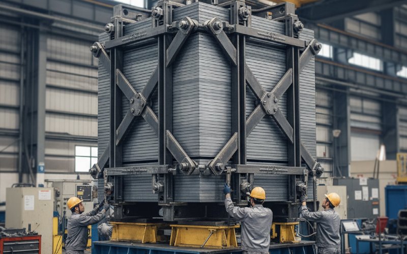
Transformer core clamping pressure: too loose vs too tight (and what to do)
Core clamping pressure almost never shows up in marketing brochures. But it shows up in noise complaints, abnormal losses, strange vibration signatures, and rewind quotes.
If you work with lamination stacks, you already know the theory from standards and design manuals. This piece is about the awkward middle ground: what actually happens on real cores when the clamping is off, and what you can practically do about it on the shop floor and in the field.
Table of Contents
1. What clamping pressure really does to a lamination stack
Short version: clamping is not just “holding steel together”.
Even with good silicon steel and careful stacking, pressure changes three things at once:
Magnetic behaviour – gaps between laminations, and gaps between limb and yoke, modulate no-load loss and magnetizing current. Loose stacks breathe more. Every cycle. That costs watts.
Mechanical behaviour – the active part is basically a pre-loaded spring. Too little pre-load, and windings and core move under electromagnetic force; too much, and insulation is crushed and stressed. Research on online pressure monitoring shows how energisation and loading actually shift clamp forces during operation.
Vibration pattern – clamp pressure on both core and windings changes the modes you see in vibration diagnostics; low pressure gives larger spatial variation and is associated with mechanical faults.
So when we say “too loose” or “too tight”, we’re not only talking about bolt torque. We’re talking about where your lamination stack ends up magnetically, mechanically, and thermally after shipping, energisation and a few years of load cycling.
2. When core clamping is too loose
Let’s assume laminations and insulation are basically okay. No rust flakes, no major burrs. Just not enough compression on the stack.
2.1 What you usually see early
On routine test and first energisation, loose lamination stacks tend to show:
Higher than expected no-load loss and magnetizing current Because the interlaminar gaps aren’t uniformly closed and the effective path length is messy. You see this especially if stacking factor is marginal to begin with.
A hum that isn’t “uniform” Normal magnetostriction hum is one thing. Loose laminations add higher-frequency buzz, sometimes directional; walk around the tank and the tone changes. Several field guides point to “loose or poorly clamped laminations” as a common root cause of unusual hum and extra loss.
More vibration spread in modal tests Studies on winding vibration under different clamping pressures show that when pressure is low, both amplitude and phase vary more around the circumference – similar to what you see in transformers with mechanical faults.
So: noisy, lossy, and hard to explain with just core grade or design.
2.2 What happens over time
Now add years of thermal cycles and short-term overloads.
With low initial clamp:
Bolts relax faster – creep in wood or composite spacers, settling of laminations, gasket creep. Online pressure measurements show that core heating can already reduce clamping pressure even when you started with a decent preload; starting low just speeds up landing in the “too loose” zone.
Laminations start fretting – tiny movements at edges scrape coatings, create metallic contact bridges and local eddy current loops. That adds local hot spots and extra noise.
Tie plates and cross arms shift – small shifts at the yoke arms or frames can open up the limb-yoke joints and compromise the stacked-core geometry, especially on three-legged cores with cross arms holding the limbs and yokes. This is the pattern that shows up as hum, energy loss and sometimes overheating in poorly controlled active-part geometry.
Short-circuit events hit harder – during a fault, electromagnetic forces spike. With poor clamping, windings and core can move relative to each other, which is not how the dielectric design was calculated.
2.3 What “too loose” says about your lamination stack
When the clamp has to do all the work, it’s often hiding stack quality issues:
Marginal stacking factor (say you’re targeting ≥0.96 but you’re not measuring systematically).
Large variation in stack thickness between limbs and yokes.
Burrs that prevent tight contact unless you torque the bolts almost to destruction.
So “low pressure” is sometimes actually “stack and tolerances not under control, so we backed off on clamp to avoid damage”. That’s not a stable configuration.
3. When core clamping is too tight
This one bites slower. And in quieter ways.
Over-tight clamping often shows up during manufacturing and later during repair work, when someone is nervous about noise and simply cranks the nuts a bit more. Guides for core reassembly specifically warn about over-tightening because it can damage insulation and other components.
3.1 Immediate effects
Crushed insulation at corners and under beams Pressboard, epoxy-glass, even coated laminations have finite compressive strength. Beyond a point, they don’t compress; they crack, or the coating shears.
Distorted stack geometry Local over-pressure bows the limb, or pulls the yoke edges in. That changes gap distribution at joints and can actually increase loss in specific regions, even if average pressure is high.
Bolt stretch against uncalibrated friction If you’re only watching torque, friction variation can push actual bolt tension well above design. And you’ll almost never know, until the first crack or leak.
3.2 Medium- and long-term issues
Damaged interlaminar coating Excess pressure on edges and at bolt holes can break the coating and create regions of metallic contact. That encourages circulating eddy currents and extra hot spots, which is exactly what lamination coating is supposed to avoid.
Stress-assisted ageing Insulation loaded close to its compressive limit ages faster under temperature cycling. Combine pressure, heat, moisture and a bit of corrosive environment and the paper/oil system is not happy.
Rework resistance When you eventually need to re-stack or inspect the core, over-compressed spacers and stuck laminations slow everything down and increase the chance of damage on disassembly. Repair guides explicitly note that excessive clamp force during earlier work can create problems during future reassembly or retightening.
And ironically, over-tight clamping doesn’t always give you the quiet transformer you expect. Distorted geometry can still be noisy, just in a different pattern.
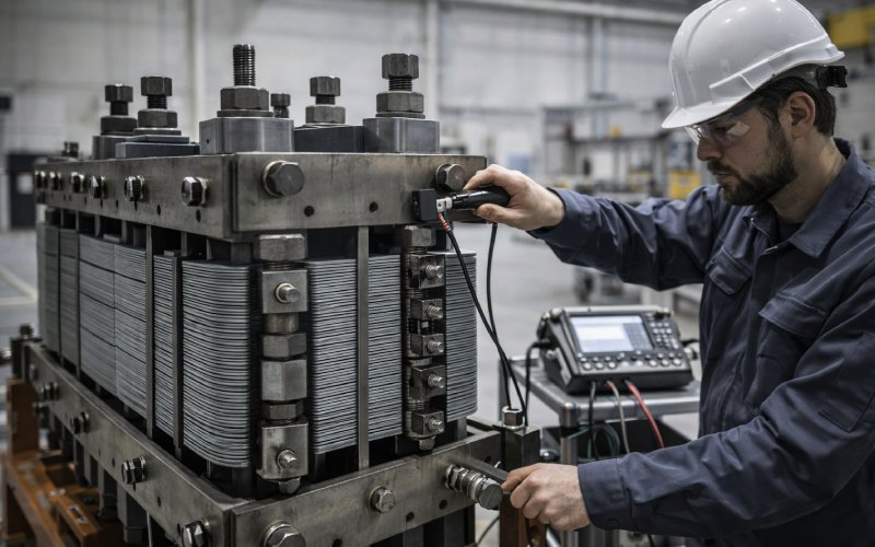
4. Quick diagnostics: loose vs tight vs “usable zone”
You rarely have a load cell inside the core frame. But you can still make a pretty good call using test data and a few simple checks.
4.1 Symptom matrix
Use this table as a starting point for stacked-lamination, oil-filled or dry-type power transformers.
Indicator / check
Too loose
Too tight
Usable range
No-load loss vs design
Higher than design, sometimes noisy core tank
Close to design or slightly lower in lab, but hotter spots near clamps
Within tolerance and consistent across units
Magnetizing current
Higher, more distortion
Normal, unless joints distorted
Within spec and stable
Audible noise pattern
Buzzier, localized “singing” spots on tank
Can be quieter overall, but with sharp tones near clamps
Uniform hum, predictable with design
Vibration measurements
Higher spatial variation in amplitude/phase along windings and tank walls
Lower amplitude but some modes shifted vs model
Close to model / baseline units
Infrared scan around clamps
Hot bands at core edges and around loose tie plates
Hot points directly under beams or at bolt holes
Even temperature distribution
Bolt torque after some service
Many bolts below target torque; uneven distribution
Torques near upper spec limit, very consistent; sometimes difficult to move
Within defined band, mild scatter
Visual on lamination stack
Gaps visible at joints, uneven stack height
Edges “printed” into spacers, laminations slightly buckled
Flat pack, joints tight but not crushed
It’s not about ticking every box. Two or three strong indicators on one side already give you a story.
4.2 How clamping shifts during operation
One reason diagnostics can be confusing: clamping pressure is not static.
When you energise at no-load, core and tie plates warm up first. Measurements of online clamping pressure show a drop as the core heats and expands against the frame.
When you apply load, windings heat up and push in the opposite direction, increasing pressure again.
So a core that was “borderline loose” at assembly can slide into a significantly looser state after a few thermal cycles. And one that was “borderline tight” might overload specific regions of insulation once temperatures climb.
Design and maintenance both need to remember this moving target.
5. Getting clamping pressure into a usable window
There is no single magic pressure number that fits every transformer size, voltage level and lamination steel. But there are process habits that keep you away from the extremes.
Since your site focuses on lamination stacks, let’s anchor the list around the stack, not just the hardware.
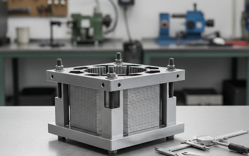
5.1 Start with a disciplined lamination stack
If the stack is random, clamping becomes guesswork.
Control burr height and flatness – manufacturing guides call for very low burr height (on the order of hundredths of a millimetre) to achieve high stacking factors and tight, uniform gaps.
Measure stacking factor and pack thickness per limb and yoke, not just by design. Store those values with the job.
Keep joint geometry repeatable – mitered joints or step-lap patterns only pay off if you hit the right overlap and gap. Don’t expect the clamp to “fix” mis-cut laminations.
If you can hand a customer (or your own assembly line) a lamination stack that behaves like a precision block, you’ve already removed half the temptation to “crank it tighter”.
5.2 Design clamps as part of the magnetic circuit, not an afterthought
A lot of issues start on the drawing board:
Cross arms, tie plates, and beams should apply pressure where it’s needed – over active core regions – not just where it’s mechanically convenient. Field examples show that poorly placed cross arms can lead to local noise and loss hotspots even if the overall clamp force is high.
Choose materials with compatible expansion – mismatch between core steel, tie plates and spacers changes pressure as temperature moves. That’s how you end up with good lab data but problems in service.
Size bolt diameters and spacing for realistic torques – if the calculated preload requires torques that your shop can’t achieve consistently, the whole design is fragile.
5.3 Define a torque / tension process, not just a number
On the shop floor:
Use calibrated torque wrenches or, better, tension control (bolt elongation or load-indicating washers) on critical clamps.
Tighten in cross patterns and stages so the lamination stack sees uniform compression.
Record actual torques or elongations; trend them across similar units to see where you really are.
For B2B customers reading your blog, offering a simple “torque map” deliverable for each lamination stack design can already set you apart.
5.4 Plan for re-torque (or not)
Not every transformer needs re-torque. But:
If you use materials that creep significantly during first thermal cycles (certain woods, some composites), consider specifying a one-time re-torque after factory heat run or after a defined service period.
If your design relies on precise clamping pressure for mechanical strength under short-circuit, uncontrolled field re-torque may actually be risky. Make that explicit in your documentation.
The key is making sure the lamination stack and clamp structure move together into a stable region and stay there.
6. Clamping used cores and repair jobs
Repairs are where many “too tight” disasters happen.
When a used transformer core is disassembled and re-stacked, typical guidance from repair houses is:
Clamp securely but with respect for insulation – over-tightening can crush old insulation or coating, causing partial discharge or new hot spots; under-tightening brings vibration and noise back.
Inspect lamination edges and coating; if you see bare steel in high-pressure areas, you may need to adjust clamp layout or add pressure-spreading pieces instead of simply torqueing more.
Use new hardware where corrosion or thread damage would change friction and make torque numbers meaningless.
If your business supplies lamination stacks for refurbishment, offering a short clamping guideline with your stacks is surprisingly valuable. You know your steel, coating, and recommended compression better than the repair crew does.
7. Design and sourcing checklist for lamination stacks and clamps
A compact list you can actually use in design reviews and supplier discussions.
For design engineers
[ ] Stacking factor and pack thickness tolerances defined and measured, not just assumed.
[ ] Clamp layout covers active regions without concentrating force at sharp corners.
[ ] Bolt size and pattern compatible with practical torque / tension control.
[ ] Thermal expansion of steel, clamps and spacers checked; modelled effect on pressure over operating temperature.
[ ] Short-circuit mechanical checks include actual clamp stiffness and preload.
For buyers / sourcing
[ ] Lamination stack drawings include stack height, joint geometry, and stacking factor requirements.
[ ] Supplier provides evidence of burr control and coating quality.
[ ] Clamp components (tie plates, beams, cross arms) have defined flatness and surface finish where they contact laminations.
[ ] Agreement on torque or bolt-tension values and the measurement method.
[ ] For repair stacks, supplier notes any special limits on clamp pressure due to coating or insulation system.
For test and maintenance teams
[ ] Baseline noise, vibration and no-load loss recorded on new units.
[ ] Bolt torques measured and stored after initial operation (where allowed by OEM).
[ ] IR imaging around core frame and clamps included in periodic inspections.
[ ] Any change in hum pattern or surprising vibration flagged as potential clamping issue, not just “old transformer”.
8. FAQ: transformer core clamping pressure
Q1. Is there a standard “correct” clamping pressure value?
Not really. Different core sizes, steel grades, insulation systems and mechanical designs call for different pressure ranges. Standards usually specify the performance (noise, loss, short-circuit withstand), not the exact preload. Many manufacturers therefore treat clamping pressure as an internal design parameter and give only torque values or procedural instructions.
Q2. Can I just torque the core bolts to the maximum allowed by the fasteners?
No. Bolt strength is only part of the story. Insulation compressive strength, lamination coating, spacer materials and frame stiffness all limit usable pressure. Over-tightening can damage insulation and coatings, as repair guidelines repeatedly warn.
Q3. How do I know if my lamination stack needs more pressure or better stacking?
Look at both: If losses, noise and vibration are off but stacking factor and pack measurements are poor, fix the stacking first. If stacking is clean and consistent, but bolts relax quickly and noise grows with time, the initial clamp preload and hardware design probably need work. Usually, the right answer is some of each.
Q4. Does higher clamping always reduce noise?
Not always. Higher pressure often reduces free vibration of laminations and windings, so noise can go down, but distorted geometry or local hot spots can introduce new tonal components. Vibration studies show that low pressure increases spatial variation of vibration; that doesn’t automatically mean “maximum possible pressure” is ideal, just that too low is clearly bad.
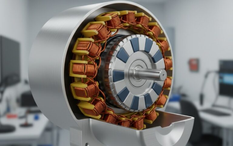
Q5. What about small dry-type or control transformers – does this still matter?
Yes, but in a different way. On smaller dry-type units, lamination stacks and frames are simpler, so clamping errors are easier to spot. Loose stacks often show up as annoying hum in control panels; too-tight clamping can warp the core and change the gap, shifting performance. The principles are the same; the scale is smaller.
Q6. How can a lamination supplier help with clamping, if they don’t assemble the transformer?
Quite a lot: Provide consistent stack quality (stacking factor, pack height, flatness). Share recommended compression limits for the steel and coating used. Include notes on joint geometry and clamp contact areas on drawings, so the transformer OEM designs the frame around real, not theoretical, stacks. When the lamination stack behaves predictably under pressure, the clamp design can be clean and conservative.
Q7. Does clamping pressure affect inrush current?
Indirectly. Inrush is mainly driven by core saturation, residual flux and system impedance. But poor stacking and loose joints can change effective core characteristics and local saturation behaviour. Getting lamination stacks and joints uniform – and then holding them that way with proper clamping – helps keep inrush within the range your calculations predicted.
Cheney is a dedicated Senior Application Engineer at Sino, with a strong passion for precision manufacturing. He holds a background in Mechanical Engineering and possesses extensive hands-on manufacturing experience. At Sino, Cheney focuses on optimizing lamination stack manufacturing processes and applying innovative techniques to achieve high-quality lamination stack products.
New Product Brochure
Please enter your email address below and we will send you the latest brochure!
Let Sino's Lamination Stacks Empower Your Project!
To speed up your project, you can label Lamination Stacks with details such as tolerance, material, surface finish, whether or not oxidized insulation is required, quantity, and more.