Let Sino's Lamination Stacks Empower Your Project!
To speed up your project, you can label Lamination Stacks with details such as tolerance, material, surface finish, whether or not oxidized insulation is required, quantity, and more.
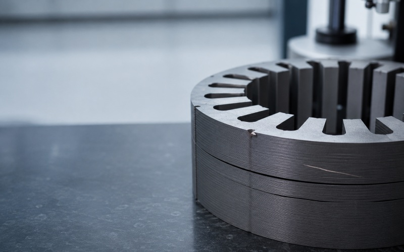
A lamination stack looks simple from the outside. A pile of thin steel sheets, punched to the same shape, bonded or clamped into a core for a motor, transformer, or generator. But the difference between a stack that runs cool for fifteen years and one that overheats in eighteen months often comes down to defects you can barely see without a loupe.
This is a guide to the three defects that show up most often on inspection reports—burrs, warpage, and scratches—and the numbers people actually argue about when a shipment gets rejected. The focus is on what a quality engineer needs to sign off, not on textbook definitions.
The whole point of laminating a core is to break up eddy current paths. Each sheet is insulated from its neighbor, usually by a thin coating, sometimes just by the surface oxide. Current that would have circulated freely through a solid block gets chopped into small loops, and losses drop.
Every defect on this list attacks that principle in some way. A burr can bridge two laminations and short them together. Warpage opens air gaps that wreck the stacking factor. A scratch strips insulation and does the same thing a burr does, just from a different direction. So the acceptance standards aren’t cosmetic. They’re a proxy for how well the core will hold its designed loss figure once it’s energized.
Keep that in mind, because it explains why the tolerances are tighter than the geometry alone would suggest.
Before quoting a single tolerance, one question decides how the rest of the conversation goes: how was the sheet cut? A limit that’s sensible for one process is either impossible or pointless for another.
Bonding and stacking method matter just as much:
The tables that follow assume conventional progressive-die punching with a clamped or interlocked stack, since that’s the most common case. Shift the process and you shift the acceptance basis with it.
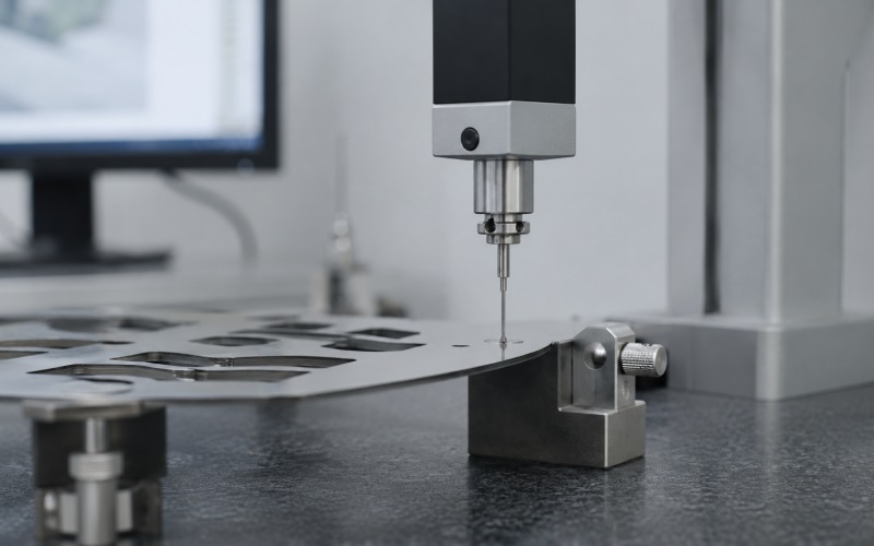
A burr is the raised lip of metal pushed out at the punched edge. It forms during blanking, and its size grows as the punch and die wear. Fresh tooling gives you a clean fracture zone with almost no burr. A tool at the end of its life gives you a curl of steel standing proud of the surface.
Why the obsession with burrs? Two reasons. First, they add height. Stack a thousand laminations, and even a 15-micron burr per sheet turns into 15 millimeters of extra stack length that isn’t doing any magnetic work. Second—and this is the one that fails product in the field—burrs pierce the interlaminar insulation and create shorts between adjacent sheets. Localized heating follows. Then a hot spot. Then a failure that looks like a bearing problem but started at the punch.
Most specifications tie the allowable burr height to sheet thickness rather than quoting one fixed number for everything, commonly landing around 5–10% of material thickness and tightened for thinner high-grade steels. The table below outlines common industry acceptance ranges for punched electrical steel.
| Sheet thickness | Typical burr height limit | Notes |
|---|---|---|
| 0.20 mm | ≤ 12–15 µm | Thin high-frequency grades, strictest control |
| 0.27–0.35 mm | ≤ 20–25 µm | Common traction and appliance motor stock |
| 0.50 mm | ≤ 25–35 µm | General industrial motors |
| 0.65 mm | ≤ 30–40 µm | Larger low-frequency cores |
These thresholds are generally verified against the electrical-steel and magnetic-materials testing framework of the IEC 60404 series (magnetic materials methods of measurement) and the corresponding ASTM A34/A343 methods, with insulation-coating condition assessed under ASTM A976 classification. Buyers working to European drawings will often see the same requirements expressed through EN 10106 / EN 10126 grade specifications. The exact figure that applies is the one written into the part drawing and the agreed acceptance standard—the references above define how to measure and classify, not a universal number.
The measurement itself trips people up. You don’t eyeball a burr. A calibrated height gauge, a laser profilometer, or a stylus profiler run perpendicular to the cut edge gives you a repeatable number. Sampling usually follows a plan pulled from the strip at set intervals, because burr height drifts as tooling wears—so a single good measurement at the start of a run tells you almost nothing about the end of it.
One practical note from the shop floor: burr direction matters. A burr that folds back toward the fracture zone is less likely to bridge insulation than one standing straight up. Some acceptance criteria account for this, most don’t, and that gap is where field arguments happen.
Warpage covers any out-of-plane deformation—dishing, waviness, edge curl, a potato-chip twist across the sheet. It comes from residual stress in the coil, uneven punching forces, thermal effects during coating cure, and rough handling.
Here’s the thing that makes warpage sneaky. A single warped sheet might pass a flatness check on its own. But stack a few hundred of them and the errors don’t average out. They accumulate, or worse, they compound where the high points line up. The result is a stack that measures taller than the math says it should, with air gaps trapped between sheets.
That directly attacks the stacking factor—the ratio of actual steel volume to the apparent volume of the stack. A good stacking factor sits above 0.96 for most grades; the best thin-gauge stacks push past 0.97. Drop below and you’ve effectively built a smaller magnetic core than the drawing called for, which shifts flux density up and losses with it. Stacking factor itself is defined and measured under the IEC 60404-13 / ASTM A719 methods.
Flatness is usually specified as a wave height or a percentage over a defined length.
| Metric | Typical acceptance | How it’s checked |
|---|---|---|
| Wave factor (I-unit style) | ≤ 1.5–2.5% peak deviation | Flat granite plate + feeler gauges or optical scan |
| Single-sheet flatness | ≤ 0.5–1.0 mm over sheet length | Depends heavily on sheet size |
| Stacking factor | ≥ 0.96 (thicker) to ≥ 0.97 (thin) | Weigh-and-measure, or clamped stack height |
| Stack parallelism | Within drawing tolerance, often ≤ 0.1 mm | Height gauge at multiple points around the core |
For finished stacks, parallelism and total stack height get measured at several points around the circumference, not just one. A stack that’s dead-on at twelve o’clock and 0.3 mm tall at six o’clock will cause problems at assembly even if the average looks fine.
Handling is half the battle with warpage. A stack of annealed laminations is floppy and takes a set easily. Once it bends past its elastic range, it stays bent, and no downstream process fully recovers it. A lot of “warpage” that shows up at incoming inspection was actually built in during transport, not manufacturing.
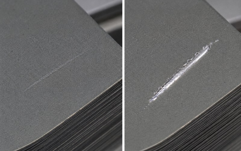
Scratches get dismissed as cosmetic more than any other defect on this list. Sometimes that’s fair. A faint mark on a sheet face, no coating breach, no burr—fine, ship it. But a scratch that cuts through the insulation coating is functionally identical to a burr: it opens a path for current to jump between laminations.
So the acceptance question for scratches is almost never about the visual appearance. It’s about whether the coating is intact. A shallow drag mark that leaves the insulation layer unbroken is usually acceptable. A gouge that exposes bare metal, especially one that runs across the flux direction, is not.
The way to judge this is with an interlaminar resistance test rather than a visual grade, run under the ASTM A717 (surface insulation resistance) and IEC 60404-11 coating methods. You apply a defined pressure and voltage across the coated surface and measure resistance. Pass the threshold and the coating is doing its job, scratch or no scratch. This is where the practical standard lives—not in a photo comparison chart, but in a resistance number.
A rough guide to how surface damage gets classified:
| Damage type | Coating status | Typical disposition |
|---|---|---|
| Light surface scratch | Insulation intact | Accept |
| Scratch to bare metal, isolated | Coating breached, small area | Review against resistance limit |
| Continuous gouge across face | Coating breached, extended | Reject |
| Handling scuff, no depth | Intact | Accept |
| Corrosion spot / stain | Depends on penetration | Test resistance, often reject if pitted |
One more source people forget: scratches often come from the stacking and handling fixtures themselves, not from the raw coil. If you’re seeing consistent parallel scratches in the same location on every sheet, stop blaming the steel supplier and go look at your own tooling and conveyors.
A specification that just lists tolerances isn’t enough. The parts that actually prevent disputes are the ones people skip.
Define the measurement method, not just the limit. “Burr ≤ 20 µm” means nothing without stating the instrument, the location on the edge, and the number of samples. Two labs measuring the same edge with different tools will disagree by more than the tolerance band. Naming the governing method—IEC 60404 series, ASTM A976, ASTM A717—closes that gap.
Set a sampling plan tied to tool wear. Punching defects grow over a production run. Inspecting the first and last pieces of a coil catches drift that a random single sample misses. Match the sampling frequency to how fast your tooling degrades.
Separate functional defects from cosmetic ones. A burr that shorts laminations and a scratch that doesn’t breach coating are not the same severity, even if both look bad. Grading defects by their effect on interlaminar resistance and stack factor keeps you from scrapping good product and passing bad product.
Test the stack, not only the sheet. Individual laminations can each pass while the assembled stack fails on parallelism, stack factor, or interlaminar resistance. Incoming sheet inspection and finished-stack inspection are two different gates, and you need both.
The stacks that cause the fewest warranty headaches tend to come from lines where the operators understand why a 20-micron burr matters, not just that a gauge went red. That understanding is what turns a spec sheet into consistent quality.
What is the single most damaging lamination defect? Burrs, in most cases. They combine two failure modes—adding non-magnetic height to the stack and shorting adjacent laminations—so a burr problem shows up both in dimensional checks and in electrical performance. Warpage is a close second because it degrades the stack factor across the whole core rather than at one point.
How do you measure burr height reliably? Use a stylus profilometer, laser profiler, or a calibrated height gauge run perpendicular to the punched edge, following the relevant IEC 60404 or ASTM A34 measurement practice. Take multiple readings along the edge and sample across the production run, since burr height increases as the punch and die wear. A single measurement isn’t representative.
Does the cutting process change the acceptance standard? Yes, significantly. Progressive-die punching is judged mainly on burr height and its drift. Laser cutting produces little mechanical burr but introduces a heat-affected edge, so the criteria shift to edge burn and local loss increase. Wire EDM gives a nearly burr-free edge and is assessed on recast layer instead. Apply the wrong basis and the standard stops meaning anything.
Is a scratch always a reject? No. If the scratch doesn’t cut through the insulation coating, it’s usually cosmetic and acceptable. The deciding test is interlaminar resistance under ASTM A717 or IEC 60404-11, not visual appearance. A scratch that exposes bare metal and lowers resistance below the threshold is the one to reject.
What stacking factor should I expect from a good stack? Roughly 0.96 or better for thicker grades, and above 0.97 for thin high-grade steels, measured per IEC 60404-13 / ASTM A719. Falling below that usually points to warpage, burrs adding height, or excessive coating thickness eating into the steel fill.
Why does the burr height limit change with sheet thickness? Thinner sheets are used in higher-frequency, lower-loss applications where insulation integrity matters most, and where the burr represents a larger fraction of the sheet thickness. Tying the limit to a percentage of thickness keeps the standard proportional to the risk.
Should I inspect sheets or finished stacks? Both. Sheet-level inspection catches burr, coating, and single-sheet flatness problems at the source. Stack-level inspection catches accumulated errors—parallelism, total height, stack factor, and interlaminar resistance—that no single sheet reveals on its own.





 English
  German
  Spanish
  French
  Italian