Let Sino's Lamination Stacks Empower Your Project!
To speed up your project, you can label Lamination Stacks with details such as tolerance, material, surface finish, whether or not oxidized insulation is required, quantity, and more.
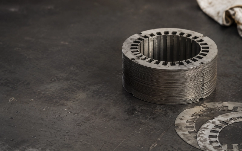
A stamped lamination can meet every reported dimension and still produce a poor stack.
The bore moves after interlocking. Stack height changes by batch. One strip lane develops burr faster than the other. Tooth width remains inside tolerance, but it has been drifting for hours.
Final inspection sees a part. Statistical process control should see the process that made it: coil, strip feed, die, individual lamination, joining operation, and finished stack.
A useful SPC plan connects those stages. A large inspection plan does not automatically do that. Sometimes it only creates more numbers.
Control four groups of characteristics:
A dimension belongs in routine SPC when it predicts product function, reveals tool wear, identifies a feed or cavity problem, accumulates during stacking, or carries a high escape cost.
A stack is not merely sheet thickness multiplied by lamination count.
H_stack = sum(t_i + c_i + b_i + e_i) - compression_set
Where:
t_i = base sheet thicknessc_i = effective coating contributionb_i = burr or edge-contact contributione_i = joining or interlock deformationcompression_set = height removed by the specified loadThis is not a design equation. It is a reminder that stable sheet thickness does not guarantee stable stack height.
Punching changes the cut-edge region through deformation, residual stress, fracture, and burr formation. Burrs may damage insulation or create contact between adjacent sheets when the stack is compressed. So burr is a process variable, not only a visual defect.
| Characteristic | Control level | What it can reveal | Measurement approach | Typical chart |
|---|---|---|---|---|
| Sheet thickness | Coil and strip | Coil drift and stack-height risk | Controlled-force thickness gauge | Xbar-R |
| Bore diameter or rotor OD | Lamination | Punch wear, fit, and air-gap change | Air gauge, bore gauge, roundness, or validated optical routine | Xbar-R or I-MR |
| Tooth width | Lamination | Magnetic-path change and local punch wear | Optical system with fixed datum and edge rules | Xbar-R by selected tooth |
| Slot opening | Lamination | Winding-access risk and die wear | Optical measurement or comparator | Xbar-R |
| Slot location or pitch | Lamination | Feed, pilot, or station error | Datum-based optical or coordinate measurement | Xbar-R by lane or cavity |
| Concentricity or runout | Part and stack | Uneven clearance, indexing error, stack shift | Rotational fixture or roundness system | I-MR or Xbar-R |
| Burr height | Tool health | Cutting-edge wear and clearance change | Contact profile or validated optical-height method at named locations | I-MR by location |
| Flatness, dish, or waviness | Part input | Strip stress and stacking instability | Defined support fixture with low force | I-MR |
| Interlock emboss depth | Joining | Interlock wear and deformation | Optical profile or depth measurement | Xbar-R |
| Finished stack height | Stack | Combined material, count, burr, and joining variation | Defined force, dwell time, supports, and positions | Xbar-R or I-MR |
| Face parallelism and stack runout | Stack | Uneven compression, skew, indexing, and fixture error | Height map and rotational measurement | I-MR |
| Skew or angular index | Stack | Rotation-sequence or stacker error | Datum fixture or optical angle measurement | I-MR |
| Missing or damaged interlocks | Stack | Joining failures | Visual or automated presence check | p, np, or defect-count chart |
This is an architecture, not a universal control plan. Bonded, interlocked, and welded stacks do not accumulate variation in exactly the same way.
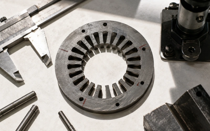
“Burr must always be below 10 micrometers” looks useful. It may be wrong for the product in front of you.
The acceptable limit depends on sheet thickness, material grade, coating, burr direction, edge location, stack compression, joining method, electrical validation, customer requirements, and the measurement method.
Use two limits where the risk supports it:
A plant might place the maintenance trigger at 60% to 80% of the product limit after studying its own tool-life data. That is a policy example, not an industry rule.
The ISO 22514 family provides methods for process capability, performance, and measurement-process capability. The current ISO 22514-2 edition addresses continuous characteristics; ISO 22514-7 addresses whether a measurement process is suitable for a defined task.
The IEC 60404 series covers electrical steel materials, magnetic-property tests, grades, geometric characteristics, and inspection requirements. IEC 60404-8-4, for example, covers fully processed cold-rolled non-oriented electrical steel in specified nominal thicknesses. It does not replace the finished lamination drawing or validated stack specification.
Standards define methods and terminology. The drawing defines acceptance. The control plan defines how early to react.
Always inspect after a die setup, die maintenance, coil change, strip rethreading, press jam, feed adjustment, stacker adjustment, joining change, or gauge-program revision. Each event can create a new process state.
For high-volume stamping, three to five consecutive laminations are often a sensible starting subgroup. Keep them from the same short period, lane, cavity, and process condition. Do not form a subgroup from the start, middle, and end of a shift; that mixes time variation into one range.
Add hit-based or time-based checks. Set the interval from tool-life history, press speed, tolerance, previous drift rate, measurement time, containment cost, and escape severity. “Every two hours” may be correct. The history should explain why.
Keep part and stack sampling separate. Part data reveals die and feed behavior. Stack data reveals accumulation, joining, compression, and indexing. Link both by coil, lane, cavity, hit range, stacker, and batch.
Use an Xbar-R chart when several consecutive values can be measured as a subgroup. It often suits tooth width, bore diameter, slot opening, thickness, and repetitive stack height.
Use an I-MR chart when only one result is practical at each interval, such as a burr profile, full stack runout, skew measurement, destructive test, or low-volume stack.
Use an attribute chart for counts or proportions, such as missing interlocks, coating damage, or rejected stacks.
Do not combine strip lanes, cavities, dies, or stackers into one chart merely because the parts share a drawing number. One chart should represent one process stream. Usually.
Measurement noise can look like process movement.
Define the datum scheme, fixture, force, support points, temperature condition, optical edge rules, burr trace direction, stack-compression force, dwell time, operator method, and gauge resolution before collecting baseline data.
A stack-height result without a specified load is incomplete. A burr reading without a fixed location is hard to compare. An optical program with changing edge thresholds is not a stable measurement process.
Calculate capability only after the process is sufficiently stable.
Cp = (USL - LSL) / (6 * sigma_within)

Cpk = min(
  (USL - mean) / (3 * sigma_within),
  (mean - LSL) / (3 * sigma_within)
)

Pp = (USL - LSL) / (6 * sigma_overall)

Ppk = min(
  (USL - mean) / (3 * sigma_overall),
  (mean - LSL) / (3 * sigma_overall)
)
USL and LSL are specification limits. sigma_within estimates short-term variation. sigma_overall includes variation across the selected period.
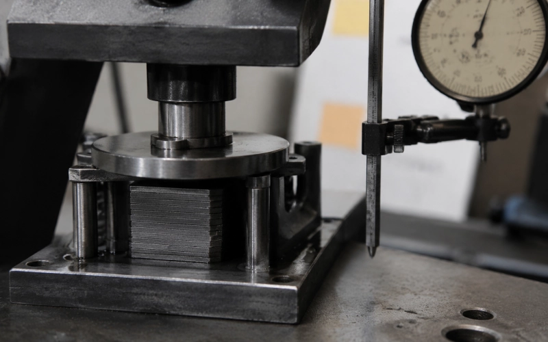
The figures below are only a teaching example.
Nominal = 5.000 mm
LSL = 4.960 mm
USL = 5.040 mm
Mean = 5.014 mm
sigma_within = 0.006 mm
Cp = (5.040 - 4.960) / (6 * 0.006)
Cp = 2.22

Upper Cpk = (5.040 - 5.014) / (3 * 0.006) = 1.44
Lower Cpk = (5.014 - 4.960) / (3 * 0.006) = 3.00

Cpk = min(1.44, 3.00)
Cpk = 1.44
Cp is strong because the spread is relatively small. Cpk is lower because the process is shifted toward the upper limit. Before adjusting the die, check the control chart, lane, cavity, gauge stability, and recent tool events.
Consider a two-lane strip with hypothetical tooth-width averages:
| Data stream | Average | Trend |
|---|---|---|
| Lane A | 4.976 mm | Moving downward |
| Lane B | 5.024 mm | Moving upward |
| Combined | 5.000 mm | Apparently centered |
The combined mean looks ideal. Neither lane is behaving ideally.
Separate charts may point toward different wear, alignment, or clearance conditions. The same masking happens when data from multiple cavities or stackers is pooled.
Do not recalculate control limits because one point crossed a limit. Change them after a real, understood process change.
Ask for more than one Cpk value:
A green dashboard is not enough. The process identity behind each number matters.
Start with sheet thickness, bore or OD, tooth width, slot opening and location, runout, burr height, flatness, interlock geometry, stack height, face parallelism, and skew. Adjust the list to the product failure modes.
No. Some dimensions need setup approval or periodic audit only. Routine SPC should focus on functional features, wear indicators, high-risk dimensions, and characteristics that accumulate in the stack.
No. The approved limit should come from the drawing, coating system, stack compression, electrical validation, customer requirement, and agreed measurement method.
Check after setup and maintenance, then at an interval based on hit count and observed wear rate. Measure fixed high-risk locations, not whichever edge is easiest to reach.
Coating, burr, waviness, debris, interlock deformation, joining conditions, part count, compression response, measuring load, and dwell time can all contribute.
Cp reflects potential capability based on spread. Cpk also reflects centering. Neither is reliable without a stable process and suitable measurement method.
No. The finished stack still needs controls for height, runout, parallelism, skew, joining, insulation condition, and product-specific performance tests.
Control dimensions that predict function. Track measurements that reveal wear. Verify the finished stack under defined conditions.
Keep the data separated by its real source: coil, lane, cavity, tool, press, and stacker.
That is how SPC catches a changing process before final inspection has to explain a failed stack.
For a useful manufacturability or quotation review, provide the lamination and stack drawings, material grade and thickness, coating, annual volume, joining method, stack-height measurement load, burr and flatness requirements, skew requirement, required capability indices, and traceability expectations.
A quote becomes more accurate when the control method is defined with the part, not added after production begins.





 English
  German
  Spanish
  French
  Italian