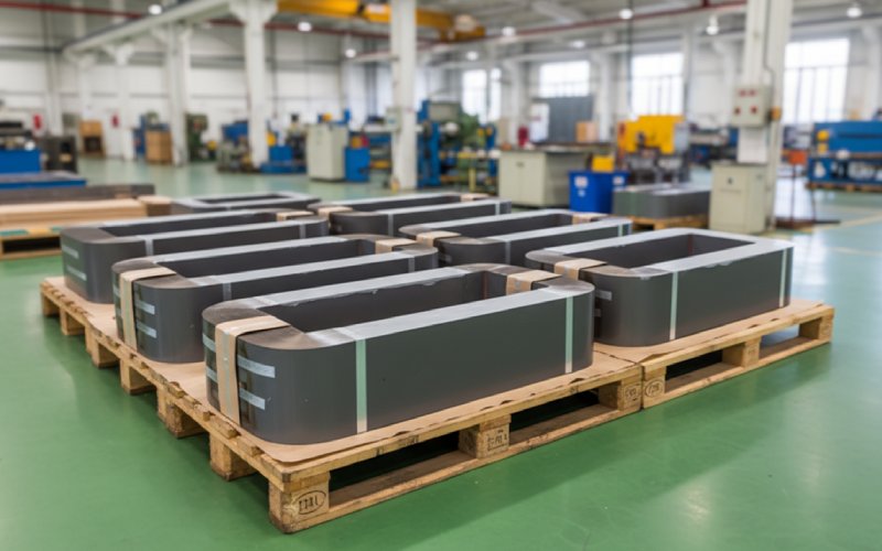
Lassen Sie Sino's Lamination Stacks Ihr Projekt verstärken!
Um Ihr Projekt zu beschleunigen, können Sie Lamination Stacks mit Details wie Toleranz, Material, Oberflächengüte, ob eine oxidierte Isolierung erforderlich ist oder nicht, Mengeund mehr.
Eine Vielzahl von CRGO-Laminierung Der Inhalt setzt eine nahezu sinusförmige Spannung und eine saubere Magnetisierungsschleife voraus. Drosseln und viele Induktivitäten leben dort nicht.
Kornorientierter Stahl verhält sich unter diesen Bedingungen anders als bei der 50/60-Hz-Sinuswellenprüfung, die in den Standardverlustbewertungen verwendet wird. Eine neuere Studie über GOES-Wickelkerne bei ~2 kHz zeigt sogar spezifische Verluste niedriger für Rechteckspannungen als für Quasi-Sinus bei gleichem Spitzenfluss, weil sich der Oberwellengehalt dorthin verschiebt, wo sich die Wirbelströme im Band konzentrieren.
Bevor Sie also aus Gewohnheit “M3, 0,27 mm” wählen, halten Sie sich fest:
Alles andere - Stapelfaktor, Verbindungsstil, Lückenplan - hängt von diesen vier ab.
In den Datenblättern wird die Sättigung für kornorientiertes Elektroband gerne mit 1,9-2,0 T angegeben, mit einem einigermaßen linearen Bereich bis etwa 1,2 T.
In der Praxis möchte man bei Leistungsdrosseln und Eisenkerndrosseln selten so mutig sein.
Diese Angaben sind Richtwerte und kein Ersatz für Ihre eigenen B-H-Kurven und Ihr Lebenszeitmodell:
| Art der Anwendung | Typische Ausführung BSpitze in CRGO | Kommentar zur Marge |
|---|---|---|
| Nebenschlussdrossel (HV, ölgefüllt) | 1.1 - 1.4 T | Starker Fokus auf Verlust + Hotspot-Kontrolle |
| Netzdrossel (NS/MV) | 1.0 - 1.3 T | DC-Vorspannung von Konvertern beobachten |
| DC-Drossel (AC/DC-Front-End) | 0,8 - 1,1 T (um den DC-Arbeitspunkt) | Flussversatz dominiert; Lücke ist das wichtigste Werkzeug |
| Mittelfrequenzinduktor (einige kHz, CRGO) | 0.8 - 1.2 T | Kompromiss zwischen Größe und Kernverlust |
| Einfache Netzdrossel / Drossel | 1.2 - 1.5 T | Oft eher kupferbegrenzt als kernbegrenzt |
Ein klassischer Leitfaden für das Design von Schnittkernen für kornorientierte Stähle zeigt ein nützliches “ausreichend lineares” Verhalten bis zu ~1,2 T selbst unter Gleichstromvorspannung, wenn der Spalt richtig gewählt wird.
Für Netz- und Nebenschlussdrosseln, Sie laufen in der Regel näher an den Transformator Praxis, aber:
Für Induktoren in Schaltnetzteilen, akzeptieren Sie normalerweise ein niedrigeres BSpitze denn:
Eine Faustregel, die Projekte vor Problemen bewahrt: Entwerfen Sie zuerst gegen Bmax,heiß,voreingenommen, nicht bei Raumtemperatur Bmax. Prüfen Sie dann, ob die von Ihnen gewünschte Note noch sinnvoll ist.
Jeder schreibt “Stapelfaktor 0,96” auf die Folie. Die Realität ist chaotisch.
Der Stapelfaktor wirkt sich direkt auf den effektiven Eisenquerschnitt aus. Niedrigerer Faktor → weniger Stahl → höhere Flussdichte als angenommen → frühzeitige Sättigung und zusätzliche Verluste. In einem Standardhandbuch für Magnetkerne wird darauf hingewiesen, dass falsch ausgerichtete Grate und eine schlechte Isolierung zwischen den Blechen den Stapelfaktor leicht so weit verringern können, dass er bei Leistungsstufen, bei denen CRGO verwendet wird, ins Gewicht fällt.
Wichtige Punkte:
Für Reaktorkerne, Der Stapelfaktor ist etwas verzeihlicher als bei Transformatoren mit hohem Wirkungsgrad, da viele Konstruktionen bereits lückenbehaftet sind. Sobald man jedoch zu Hochspannungs-Nebenschlussdrosseln mit hohem Durchfluss und geringem Verlust übergeht, machen sich kleine Fehler in der effektiven Fläche als zusätzliche Watt und unerwartete Hotspot-Positionen bemerkbar.
Sie müssen nicht alles in die Ausschreibung aufnehmen, aber planen Sie es:
Wenn Sie ein Transformator-Laminierwerkzeug für eine Drossel wiederverwenden, überprüfen Sie, ob die real die Stapelhöhe nach dem Beschichten und Pressen noch mit dem magnetischen Design übereinstimmt. Das ist oft nicht der Fall.
In den Blogs über CRGO-Laminierung wird viel Zeit auf Step-Lap für Transformatoren verwendet. Die Physik lässt sich auf Drosseln und Spulen übertragen, nur mit anderen Prioritäten.
In Reaktoren:
Welche Verbindung Sie auch immer verwenden, stellen Sie sicher, dass in Ihrer Zeichnung und in der Ausschreibung davon die Rede ist:
Wenn Sie die gemeinsame Strategie “implizit” lassen, endet das oft damit, dass der Lieferant seine Transformator-Standardwerte verwendet, die möglicherweise nicht zur DC-Vorspannung und Wellenform Ihrer Drossel passen.
Lücken sind die Stellen, an denen Reaktorkerne stillschweigend zusätzliche Verluste erzeugen.
Akademische Arbeiten über Eisen-Kern-Nebenschlussdrosseln mit diskret verteilten Luftspalten werden verglichen:
Es wird gezeigt, wie durch die Verteilung des Spalts die Induktivität, Streuinduktivität und der Verlust getrennt eingestellt werden können und wie die Ausfransung um jeden Spalt herum den lokalen Wirbelstromverlust erhöht.
Für Leistungsreaktoren ergeben sich daraus einige Gestaltungsmöglichkeiten:
Für Induktivitäten wird in einem klassischen Leitfaden für das Design von C-Kernen mit Eisenkernen betont:
Lassen Sie also die Lückengeometrie nicht im Unklaren.
Und nein, der Satz “typische Transformatorabstände” in der Spezifikation reicht nicht aus, wenn Ihre Drossel nahe der Sättigung unter Gleichstromvorspannung arbeiten soll.
Die meisten Artikel über Rauschen zielen auf Transformatoren ab, aber die gleichen Magnetostriktionsphänomene treten auch bei größeren Reaktoren und Drosseln auf: Die Lamellen dehnen sich leicht, wenn sich der Fluss umkehrt, und der Stapel vibriert.
Neuere ingenieurwissenschaftliche Aufzeichnungen über die CRGO-Magnetostriktion enthalten einige Punkte, die sich direkt auf Reaktor- und Induktorstapel übertragen lassen:
Für Reaktoren:
Design-Checkliste für den Stapel:
CRGO hat eine relativ hohe Wärmeleitfähigkeit und eine hohe Curie-Temperatur (oft um 730 °C bei Standardsorten).
Zwei Folgen, die bei Reaktoren/Induktoren von Bedeutung sind:
Für die Konstruktion von Kaschierungsstapeln:
Thermisch gesehen verzeiht CRGO Ihnen normalerweise. Das Wicklungsisolationssystem nicht.
Die meisten RFQs spezifizieren Qualität, Dicke und Beschichtung, vielleicht “step-lap”. Normungsleitfäden weisen darauf hin, dass Güteklassen und Verlusttabellen nur die Hälfte der Geschichte erzählen; der Rest hängt davon ab, wie die Lamellen zu einem Kern verarbeitet werden.
Bei Drosselspulen und Induktivitäten ist eine gewisse Genauigkeit erforderlich.
Spezifizieren:
Einschließen:
Für CRGO-Kerne mit Lücken:
Sie brauchen nicht eine Million Tests. Aber definieren Sie eine kleine, klare Menge:
Wenn ein Reaktor später heiß läuft oder vorzeitig in Sättigung gerät, können Sie das entweder auf die Konstruktionsannahmen oder die Ausführung des Stapels zurückführen, ohne zu raten.
Sie ist nicht erschöpfend, aber sie erfasst viele der Probleme, die erst spät auftauchen:
Wenn eine Antwort “nicht sicher” lautet, ist das in der Regel der Ausgangspunkt für künftige Fehleranalysen.
Manchmal, aber nicht blindlings.
Wenn die Netzdrossel ähnliche Flusswerte und keine ernsthafte Gleichstromvorspannung aufweist, kann ein transformatorähnlicher Kern mit Stufenfugen und ähnlicher Güte funktionieren.
Sobald Gleichstromvorspannung oder große Oberschwingungsströme auftreten, benötigen Sie mehr Lücke und oft einen niedrigeren Bmax. Dadurch ändern sich die optimale Stahlsorte und die Stapelhöhe.
Führen Sie zumindest den Entwurf mit realistischen Stromwellenformen und Stapelfaktor erneut durch und überprüfen Sie die Lückenbestimmungen.
Für frühe Schätzungen:
0,95 ist ein guter Richtwert für modernes dünnes CRGO mit guten Beschichtungen und zuverlässiger Prägung.
Senken Sie auf 0,92-0,93, wenn das Werkzeug alt ist, die Dicke >0,30 mm oder die Gratkontrolle schlecht ist.
Gehen Sie aber zu Messwerten über (über Masse oder Abmessungen), sobald Sie erste Artikel haben.
Kornorientierter Stahl gewinnt in der Regel, wenn:
Die Flussdichte ist hoch (Bereich 0,8-1,2 T)
Die Frequenz ist moderat (bis zu ein paar kHz)
Die Leistung ist groß, so dass das Volumen des Ferrits zu groß wäre.
Ferrite und Pulverkerne gewinnen im Hochfrequenzbereich, wo die Kernverluste bei CRGO selbst bei niedriger Induktion zu groß sind. Der Handel läuft auf Folgendes hinaus Frequenz gegen Bmax vs. Volumen vs. Verlust.
Grate wirken sich aus:
Stapelfaktor (weniger wirksames Eisen)
Interlaminare Wirbelströme (mehr Verlust)
Aus der Konstruktionsliteratur geht hervor, dass falsch angelegte Grate den Stapelfaktor so weit reduzieren können, dass eine vermeintlich “sichere” Konstruktion in die Sättigung geht.
Wenn Sie Hochleistungsreaktoren entwerfen, lohnt es sich, einen numerischen Grenzwert für die Grathöhe in die Ausschreibung aufzunehmen und eine einfache Messmethode zu verlangen (Profilometer, Stichprobenprüfungen pro Charge).
Das können sie, aber nicht automatisch.
Untersuchungen an Nebenschlussdrosseln mit diskret verteilten Lücken zeigen, dass:
Mit verteilten Lücken lassen sich Induktivität und Streuinduktivität flexibler steuern.
Die Umrandung jeder Lücke führt zu lokalen Wirbelstromverlusten, so dass zu viele Lücken den Gesamtkernverlust erhöhen können, wenn sie schlecht implementiert sind.
Verteilte Lücken sind also ein Designwerkzeug, kein kostenloses Upgrade. Sie müssen durch eine Analyse (analytisch oder FEA) untermauert und für den Laminatlieferanten eindeutig dimensioniert werden.
Bei CRGO-Reaktoren und Induktionsspulen sollten Sie diese Punkte nicht vage lassen:
Gemeinsame Methode und Überschneidung
Abmessungen und Verteilung der Lücken
Zielbereich des Stapelfaktors
Prüfbedingungen für den Kernverlust (B, f, Temperatur, Wellenform)
Diese vier Nicht-Entscheidungen sind der Grund für die meisten Überraschungen, wenn der Prototyp auf dem Prüfstand steht.