Let Sino's Lamination Stacks Empower Your Project!
To speed up your project, you can label Lamination Stacks with details such as tolerance, material, surface finish, whether or not oxidized insulation is required, quantity, and more.
Amorphous motor core processing usually fails at four points: cutting damage, unstable stacking factor, bonding stress, and brittleness after heat treatment.
For a usable amorphous lamination stack, the supplier should control not only the drawing dimensions, but also edge cracks, burrs, layer alignment, interlaminar insulation, resin shrinkage, particle release, and core loss after assembly.
Typical amorphous alloy ribbons used in motor-core work are very thin, often around 20–35 μm, with high hardness and high tensile strength. This is why the material can reduce eddy-current loss, but also why it is difficult to punch, stack, bond, and assemble without damage. Some documented motor-core routes report amorphous strip thickness in this range, with high hardness and tensile strength values in the GPa range.
The best process is not “cutting first” or “stacking first” in every case. The best process is the one that keeps the ribbon supported before it becomes brittle, keeps the cut edge out of high-stress zones, and proves the final core loss after bonding and housing fit.
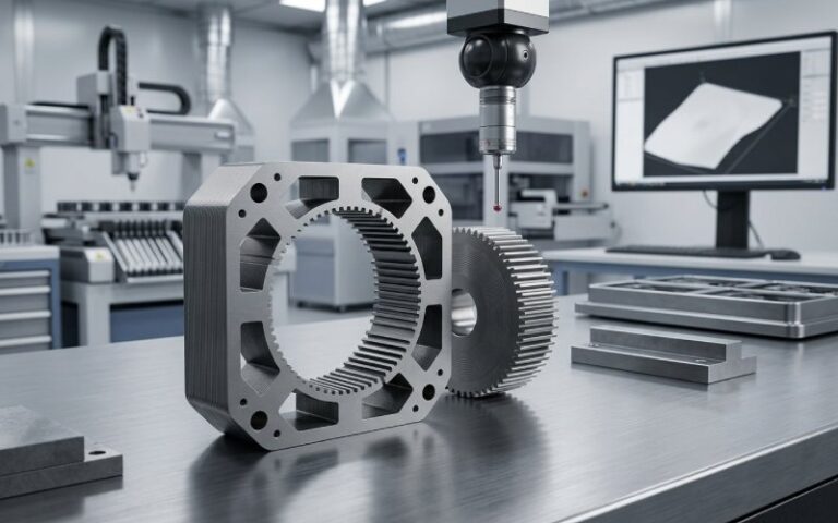
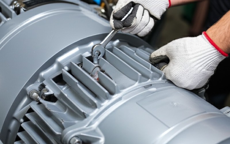
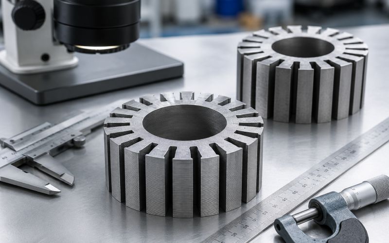
An amorphous motor core is a stator or rotor magnetic core made from thin amorphous alloy ribbon instead of conventional thicker electrical steel laminations.
The word “amorphous” means the metal does not have a normal crystalline grain structure. This gives the material useful soft magnetic properties, especially low core loss at higher electrical frequencies. For compact, high-speed, or high-frequency motors, that can be attractive.
The problem is mechanical.
The ribbon is thin, hard, and sensitive to stress. Cutting can damage the edge. Stacking can create gaps. Bonding can add internal stress. Annealing can improve magnetic properties in some cases, but it can also increase brittleness. Impregnation curing and interference fit have both been shown to affect amorphous iron-core loss and magnetic behavior.
So the real challenge is not only material selection.
It is process survival.
| Item | Conventional electrical steel stack | Amorphous lamination stack | Processing impact |
|---|---|---|---|
| Typical sheet form | Thicker rolled sheet | Very thin rapidly quenched ribbon | More layers are needed for the same stack height |
| Cutting behavior | Mature stamping and laser routes | Crack-sensitive, hard, thin material | Edge quality becomes a major control point |
| Stacking factor | Usually easier to keep high | Lower and more sensitive to coating, resin, waviness, and pressure | Magnetic design must use measured stack factor |
| Bonding need | Welding, interlocking, bonding, riveting all possible | Bonding or impregnation often needed for stability | Resin shrinkage can increase loss |
| Heat treatment | Often used for stress relief | Can reduce stress, but may increase brittleness | Sequence matters more |
| Main production risk | Burrs, welding stress, dimensional shift | Edge cracking, flaking, brittle fracture, loss increase after assembly | More inspection gates are needed |
A conventional motor core can often tolerate some local damage because the process window is known. Amorphous ribbon gives less room for guessing.
| Failure mode | Common cause | Production symptom | Engineering control |
|---|---|---|---|
| Edge microcracks | Punching shock, poor support, worn tooling, excessive laser heat | Flaking, loss increase, weak tooth edges | Edge microscopy, burr control, cut-loss coupon test |
| High core loss after cutting | Heat-affected zone, deformation, damaged magnetic structure | Prototype loss higher than ribbon data | Compare loss before and after cutting using the same geometry |
| Low stacking factor | Ribbon waviness, thick resin, dust, poor compression control | Lower flux capacity, larger motor size | Measure stack height and mass; do not assume steel-stack values |
| Delamination | Weak bond, poor surface cleaning, uneven resin | Layer lift during machining or vibration | Bond-strength test and section inspection |
| Loss increase after curing | Resin shrinkage and internal stress | Good dimensions but worse magnetic test result | Test before and after impregnation or bonding |
| Brittleness after annealing | Heat treatment above the safe process window or poor sequence | Cracks during handling, particles in motor gap | Move forming before brittle state; validate non-annealed route where possible |
| Loss increase after press fit | Housing interference and compression stress | Core passes before assembly, fails after insertion | Measure core loss before and after housing fit |
| Particle contamination | Brittle edge, poor cleaning, damaged slot surface | Metallic debris, insulation risk, rotor-stator gap risk | Vacuum cleaning, wipe test, particle inspection, edge sealing |
For motor laminations in general, cutting and joining can change iron loss significantly. Reviews of manufacturing effects report that cutting-related loss can vary strongly with material, geometry, process, and magnetic loading; some comparisons show wire cutting causing less magnetic damage than punching or laser cutting under specific test conditions.
A reliable amorphous motor core process usually follows this logic:
The important point is the repeated testing. Ribbon data alone is not enough. A finished amorphous stator can behave differently after cutting, bonding, heat treatment, and press fitting.
These values are not universal machine settings. They are useful starting points for drawings, supplier discussions, and process qualification.
| Item | Practical reference | Why it matters |
|---|---|---|
| Ribbon thickness | Commonly around 20–35 μm | Thin ribbon reduces eddy-current loss but increases layer count and handling risk |
| Hardness | High; documented amorphous strip examples report HV 700–1000 | Tool wear and edge cracking become serious |
| Tensile strength | Documented examples report 1.4–2.2 GPa | High strength does not mean easy forming; brittle fracture is still possible |
| Saturation magnetic induction | Some Fe-based amorphous motor-core routes specify ≥1.60 T | Sets the usable flux-density range for design |
| Stacking factor | Validate on the actual stack; one documented amorphous motor-core example reports 89.0% | Do not use electrical-steel assumptions without measurement |
| Operating frequency range | Some high-frequency amorphous motor-core routes target hundreds to thousands of Hz | The value of amorphous material rises when core loss is a large part of total loss |
| Edge inspection magnification | Start with 50×–200× optical inspection, then use cross-section or SEM for problem samples | Burrs and cracks may be missed by visual inspection |
| Magnetic test condition | Define flux density, frequency, waveform, temperature, and sample geometry | “Low loss” has no meaning without test conditions |
| Housing fit check | Test before and after press fit | Compression stress can raise loss |
A published amorphous iron-core study showed that impregnation curing and interference fit changed loss behavior, and that the lowest-loss heat-treatment condition after impregnation was not the same as before impregnation. In one tested condition, loss after impregnation curing reached 22.8 W/kg at 1.2 T and 1.5 kHz after annealing at 260 °C, with a reported increase compared with the pre-impregnation state.
That single number should not be copied as a process recipe. Its value is the warning: curing, annealing, and assembly stress interact.
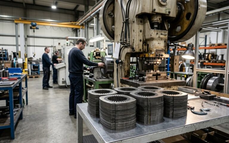
Punching is attractive for volume production. It is also the easiest place to create cracks.
Amorphous ribbon is thin and hard. If the punch clearance is wrong, the tool is worn, or the ribbon is not supported, the edge can chip or delaminate. The defect may be too small to see by eye but large enough to raise loss or start flaking later.
Use punching when:
Recommended controls:
Punching can work. Casual punching does not.
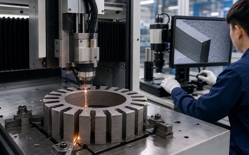
Laser cutting gives flexible geometry and fast design changes. It is useful for prototypes, small batches, and complex stator shapes.
The risk is heat.
The cut edge can contain a heat-affected zone, recast material, local stress, or structural change. For amorphous alloy, this can damage magnetic performance. Recent work on amorphous motor cores specifically studies cutting damage because it affects measured motor-core loss under variable-frequency conditions.
Do not qualify laser cutting by power rating alone.
Qualify it by:
For thin single ribbons, lower heat input and stable support matter. For bonded stacks, cutting speed and heat evacuation matter more. In both cases, the useful question is not “fiber or gas laser?” The useful question is: what edge condition and loss result does the process produce on this exact stack?
Wire electrical discharge cutting is common for accurate prototype cores and stack-first processing. It applies little mechanical force, which helps with fragile lamination stacks.
Its risk is localized thermal and discharge damage. Research on wire-cut amorphous alloy cores has reported significant changes in magnetic performance after machining, which means wire cutting also needs magnetic validation, not only dimensional inspection.
Use wire cutting when:
Recommended controls:
Abrasive waterjet cutting avoids major thermal damage. That can be useful for bonded stacks.
Its risks are edge roughness, moisture, abrasive contamination, and layer disturbance. It is rarely a “clean final process” without follow-up inspection and drying.
Use it mostly for:
Required checks:
Chemical or photo etching can reduce mechanical stress and produce fine features. It is more suitable for thin sheets, sample laminations, and precision development work than for every high-volume motor-core geometry.
Risks include undercut, cleaning quality, chemical compatibility, and slower throughput.
Use it when:
| Requirement | Best candidate | Avoid as first choice |
|---|---|---|
| High-volume simple tooth geometry | Punching after tooling validation | Slow wire cutting |
| Prototype stator with changing slot shape | Laser or wire cutting | Dedicated stamping tool |
| Lowest mechanical force | Wire cutting or etching | Poorly supported punching |
| Lowest heat input | Etching or waterjet | High-power continuous laser cutting |
| Bonded stack final shaping | Wire cutting or waterjet | Single-sheet handling route |
| Very narrow tooth tips | Wire cutting with support, or segmented design | Aggressive punching |
| Best magnetic validation route | Cut by several methods and compare loss | Choosing by visual edge only |
A good cutting process is the one that survives three tests: edge inspection, core-loss measurement, and post-assembly stability.
Stacking factor is the ratio of magnetic metal height to total stack height. In amorphous motor cores, it is usually more difficult to control than in thicker electrical steel stacks because each layer is extremely thin.
The design mistake is simple: using the apparent tooth area as if it were solid metal.
The corrected calculation is:
Effective magnetic area = apparent stack area × measured stacking factor
If the apparent stator tooth area is 100 mm² and the measured stacking factor is 0.89, the effective magnetic metal area is 89 mm².
That difference changes flux density, saturation margin, temperature rise, and loss prediction.
Use these controls:
More pressure can reduce air gaps, but it can also crush coatings, increase residual stress, squeeze out resin unevenly, or start edge cracking.
The target is not the highest possible stacking factor.
The target is the highest stable stacking factor that still passes:
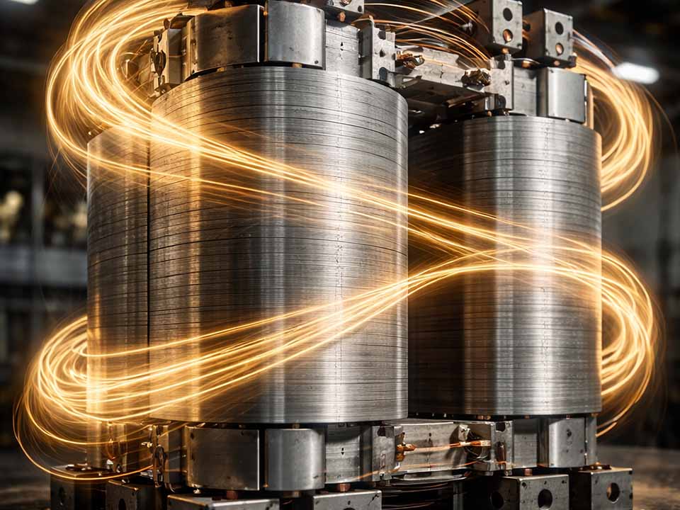
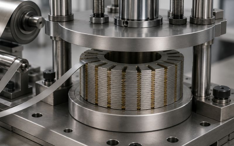
Amorphous lamination stacks usually need bonding, impregnation, or another fixing method. Thin ribbons cannot be treated as loose sheets once the motor enters winding, assembly, vibration, and thermal cycling.
Bonding gives:
Bonding also creates risk.
Resin shrinkage during curing can add internal stress. Internal stress changes magnetic behavior. Testing on amorphous iron cores has shown that impregnation curing can increase loss and shift the heat-treatment condition that gives the lowest loss.
| Control item | Recommended requirement |
|---|---|
| Resin content | Define target mass gain or volume fraction |
| Viscosity | Low enough for penetration, not so low that resin drains out |
| Cure profile | Record temperature ramp, hold time, and cooling method |
| Cure pressure | Define pressure range and fixture flatness |
| Shrinkage | Compare core loss before and after cure |
| Bond strength | Test on stack coupons, not only resin datasheets |
| Insulation | Measure interlaminar resistance after cure |
| Voids | Inspect sectioned samples from first articles |
| Cleanliness | Check particle release after curing and machining |
A bonded amorphous stack should be judged as a magnetic part, not only a mechanical part.
Annealing can relieve stress and improve soft magnetic properties. It can also make amorphous alloy more brittle.
This is why annealing must be treated as a process option, not a default habit.
Some amorphous motor-core routes specifically avoid annealing to reduce brittleness, fragment release, and cracking during processing, assembly, or motor operation. Documented examples describe the risk of annealed amorphous cores generating fragments and cracks, including the danger of fragments entering the rotor-stator gap.
Annealing may help when:
Annealing may hurt when:
Use this validation sequence:
Cut sample → measure loss → bond stack → measure loss → anneal trial → measure loss → assembly trial → measure loss again
Do not approve annealing based on a loose ribbon sample. The finished core has different stress, different thermal mass, and different mechanical risk.
Sharp corners and thin bridges make brittle failure easier.
Use:
A design that works in electrical steel may not survive amorphous ribbon processing.
For some stators, handling single amorphous laminations is not practical. A stack-first route can reduce damage:
Ribbon preparation → rectangular stacking → bonding or impregnation → curing → final wire cutting or precision machining → cleaning → inspection
This route protects individual layers earlier. It also means the final cut passes through a bonded stack, so edge inspection becomes even more important.
If annealing is used, perform major cutting, bending, forming, and stacking before the material reaches its most brittle state.
A safer sequence is often:
cut/form → stack → bond/support → heat treatment if validated → final cleaning → protected assembly
This is not always the lowest-loss route. It is often the better yield route.
Press fitting can change magnetic performance. Compression is not just a mechanical issue. Interference fit has been shown to increase amorphous iron-core losses, and removed pressure may not fully return the internal stress state to its original condition.
Control these items:
For high-frequency motors, post-fit core loss is more useful than loose-core loss.
Brittle amorphous edges can shed small metallic fragments. In a motor, that is not cosmetic. It can affect insulation, noise, rotor-stator clearance, and reliability.
Add these controls:
Edge inspection should be written into the drawing or supplier quality plan.
| Method | What it detects | When to use |
|---|---|---|
| 10× visual inspection | Gross chips, discoloration, delamination | Every batch |
| 50×–200× optical microscopy | Burrs, lifted layers, cracks, recast, rough edge | First article and process audits |
| Cross-section polishing | Hidden cracks, resin penetration, layer gaps | Process qualification |
| SEM inspection | Fine cracks, fracture surface, thermal damage | Failure analysis or critical parts |
| Insulation resistance test | Layer-to-layer shorts from burrs or crushed coating | After stacking and bonding |
| Core-loss A/B test | Magnetic damage from cutting, bonding, annealing, assembly | Every process route approval |
| Particle release test | Brittle fragments and loose metallic debris | Before motor assembly |
The most useful test is usually not the most expensive one. For production, combine optical inspection, insulation resistance, stack-height measurement, and loss testing. Use SEM when the defect cannot be explained.
A serious amorphous motor core project should not measure loss only once.
Use this sequence:
| Test stage | Purpose | Pass/fail logic |
|---|---|---|
| Incoming ribbon | Establish baseline | Compare with material certificate and internal reference |
| After cutting | Measure edge damage effect | Loss increase must stay within project limit |
| After stacking | Check air gaps and layer alignment | Stack factor and insulation must pass |
| After bonding | Identify curing stress | Loss shift must be recorded and limited |
| After annealing, if used | Confirm magnetic benefit | Loss improvement must justify brittleness risk |
| After final machining | Catch last edge damage | Compare with pre-machining value |
| After housing fit | Capture assembly stress | Final value is the release value |
| After thermal/vibration trial | Check stability | No particle release, cracks, or loss drift beyond limit |
The final number to use in motor efficiency calculation is the loss after the core has seen the real process.
Not ribbon loss. Not loose stack loss. Final-core loss.
Use this section when requesting quotations or approving samples.
Specify:
Request:
Define:
Define:
Define one of three policies:
Annealing required
Annealing forbidden
Annealing supplier-validated only
If annealing is allowed, require:
Require:
This is where many projects improve quickly. Once the supplier knows the core will be judged by magnetic and mechanical data, not only dimensions, the process changes.
Do not simulate with ideal core area. Use the measured stacking factor and include resin or air-gap effects.
Cut edges are damaged zones. Keep the highest flux density away from heavily cut or brittle edges where possible.
Segmented stators or tooth modules can reduce forming stress and improve process yield. The assembly is more complex, but the ribbon may survive better.
A wire-cut prototype may not represent a punched production core. A loose stack may not represent a bonded and pressed stator. Use the intended production route before freezing efficiency claims.
Slots and corners that trap particles are risky. Cleaning access matters when the material can chip or flake.
| Acceptance item | Suggested requirement format |
|---|---|
| Ribbon thickness | Nominal value plus tolerance |
| Stack height | Measured at several positions |
| Stacking factor | Reported with measurement method |
| Edge crack | No crack extending into active flux area beyond agreed limit |
| Burr / lifted layer | No burr bridging adjacent layers |
| Heat damage | No visible discoloration or recast beyond agreed limit; confirm by section if needed |
| Interlaminar insulation | Minimum resistance after cutting and bonding |
| Bond strength | Minimum value from coupon or representative stack |
| Core loss | Maximum value at defined flux density, frequency, waveform, and temperature |
| Particle release | No visible metallic fragments after cleaning and handling test |
| Assembly effect | Loss increase after housing fit below agreed limit |
The exact numbers depend on motor size, flux density, speed, cooling, safety margin, and cost target. The format should not depend on them. Every amorphous motor core specification needs these categories.
The drawing gives shape. It does not define edge damage, residual stress, particle risk, or core loss. Add magnetic and process requirements.
Ribbon loss is a starting point. Finished stator loss is the number that matters.
Amorphous stacks are thinner, harder, and more sensitive to gaps, resin, and pressure. Measure the stack.
Annealing may improve loss, but it can also increase brittleness. Approve it only after the final core passes handling, assembly, and loss tests.
A core that passes before housing insertion may fail after compression. Test after assembly.
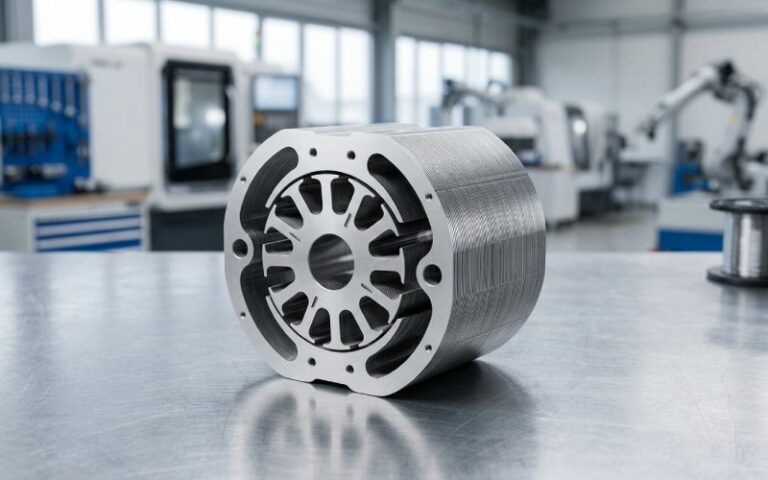
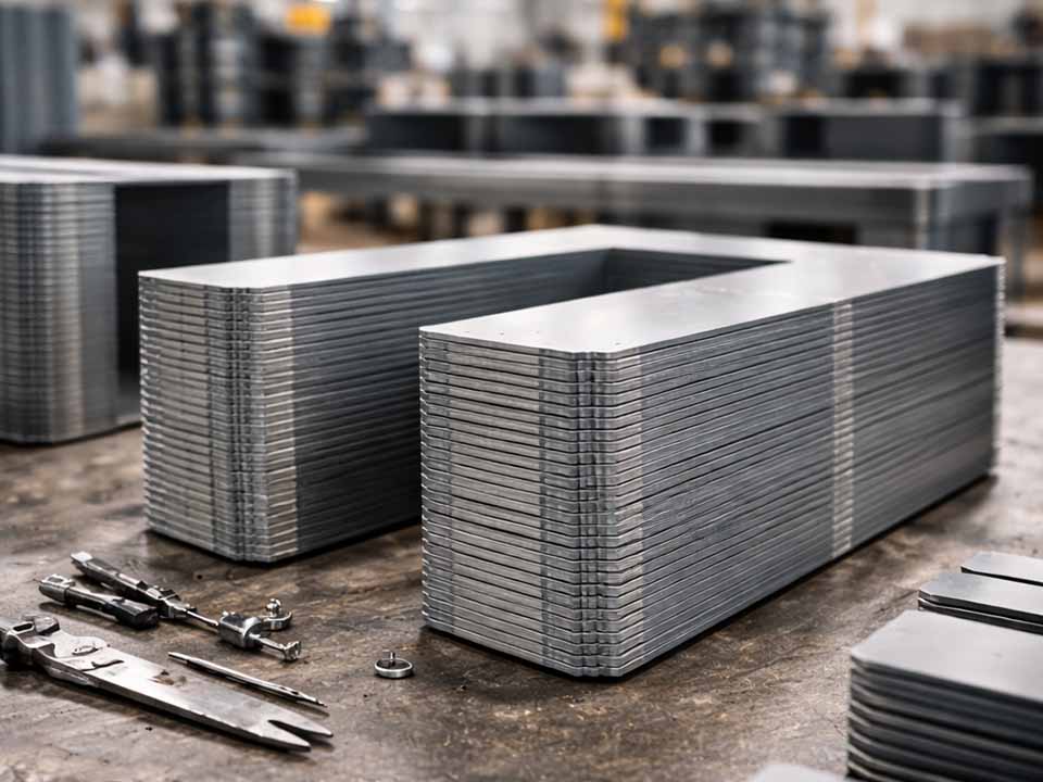
An amorphous lamination stack is a magnetic core package made from many thin amorphous alloy ribbons. The layers are stacked, bonded, impregnated, or otherwise fixed to form a stator, rotor, segment, or magnetic core.
They are brittle because amorphous alloy ribbon is thin, hard, and sensitive to local stress. Brittleness can become worse after heat treatment, poor cutting, sharp geometry, over-compression, or vibration. Edge cracks and fragments are the main practical risks.
Many amorphous motor-core ribbons are in the 20–35 μm range. This thin gauge helps reduce eddy-current loss but makes stacking, punching, and handling harder.
Yes, but punching needs sharp tooling, tight clearance control, strong ribbon support, and regular edge inspection. Poor punching can create cracks, burrs, layer lift, and higher core loss.
Laser cutting is useful for prototypes and complex geometries, but heat input must be controlled. The edge should be checked for heat-affected zones, discoloration, recast, microcracks, and loss increase.
Wire cutting often creates less mechanical stress and can be accurate for bonded stacks, but it is slower and can still cause discharge-related magnetic degradation. The best choice depends on the measured loss and edge condition, not the process name alone.
Use the measured value from the actual stack. Do not copy a value from electrical steel. One documented amorphous motor-core example reports a lamination coefficient of 89.0%, but each stack must be verified by height, mass, coating, and resin content.
It can. Bonding and impregnation improve mechanical stability, but resin curing can introduce internal stress. That stress may increase loss or shift the best annealing condition.
Only if testing proves it helps the finished core. Annealing can reduce stress and improve magnetic properties, but it can also increase brittleness. Some process routes avoid annealing to reduce cracking and fragment risk.
Use optical microscopy for routine inspection, then use cross-section analysis or SEM for deeper failure analysis. Also test insulation resistance and core loss, because a visually clean edge can still be magnetically damaged.
Ask for stack factor data, edge inspection photos, core-loss results, insulation resistance, bonding process data, cure profile, annealing policy, particle inspection, and loss after housing assembly. Dimensions alone are not enough.
Amorphous motor core processing is not a normal lamination job with thinner material.
The ribbon can offer low loss, but only if the process protects it. Cutting damage, bonding stress, annealing brittleness, and assembly pressure can erase the benefit.
A reliable amorphous lamination stack needs four things:
That is the difference between a promising amorphous ribbon and a motor core that can survive production.