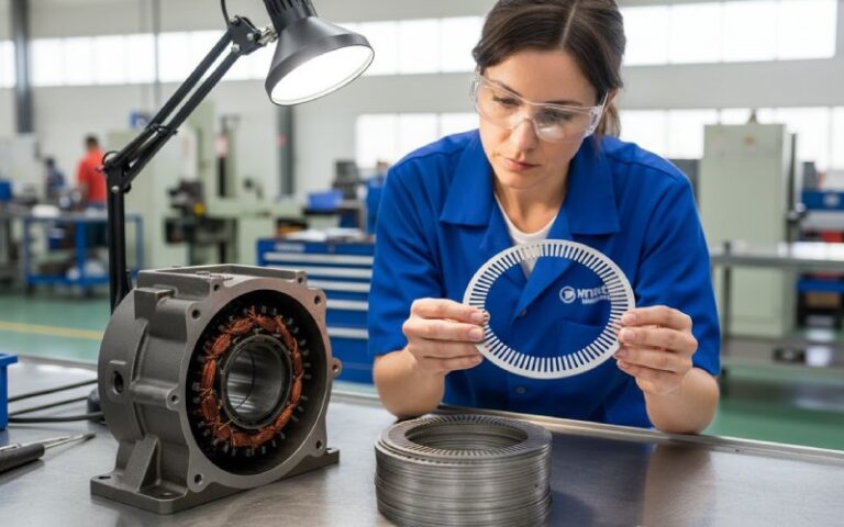
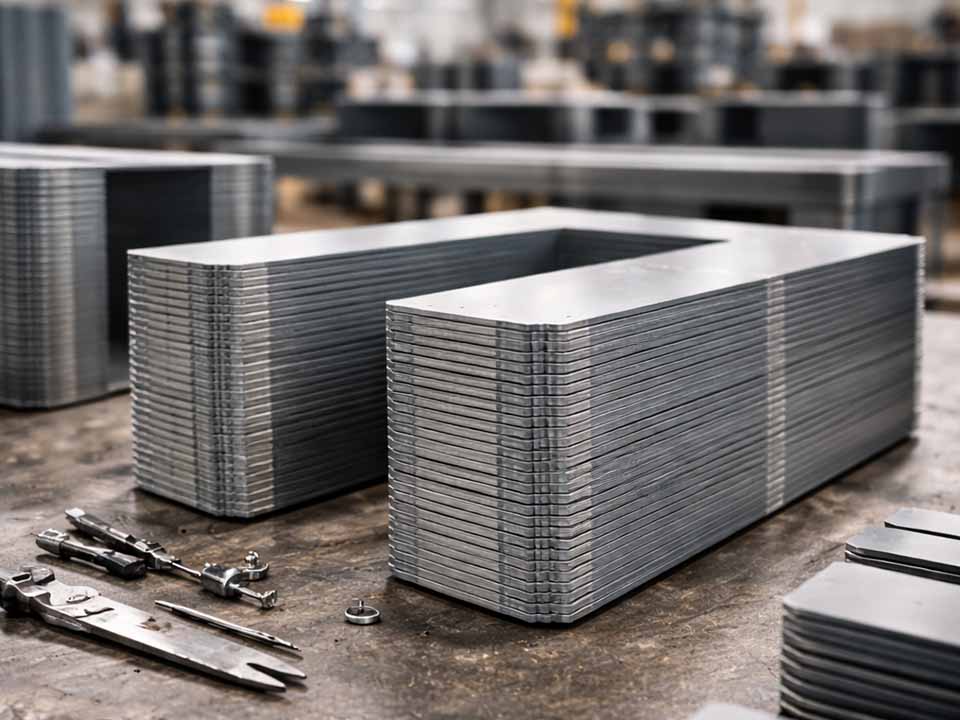
Let Sino's Lamination Stacks Empower Your Project!
To speed up your project, you can label Lamination Stacks with details such as tolerance, material, surface finish, whether or not oxidized insulation is required, quantity, and more.
Powder metallurgy makes sense when the magnetic core needs to be more than a flat stack of steel sheets.
That is the shortest useful answer.
Laminated steel cores are still the default choice for many motors, transformers, generators, and actuators. They are efficient, familiar, scalable, and hard to beat when the magnetic flux mainly travels in the plane of the lamination stack.
Powder metallurgy, usually in the form of soft magnetic composite cores, starts to look better when the design asks for something awkward:
But PM is not a direct upgrade from laminated steel. It is a trade.
It can reduce eddy current loss. It can make complex shapes possible. It can simplify assembly.
It can also bring lower permeability, higher magnetizing current, weaker low-frequency performance, density variation, tooling cost, and thermal questions that do not show up in a pretty CAD model.
So the real question is not:
“Is powder metallurgy better than laminated steel?”
The better question is:
“Does this magnetic circuit reward a 3D compact core enough to offset the material penalties?”
Sometimes yes. Often no.
That is where the decision gets useful.
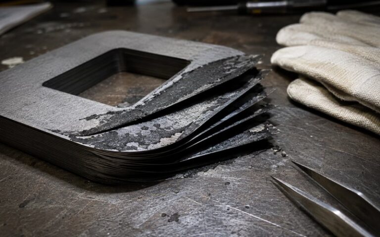
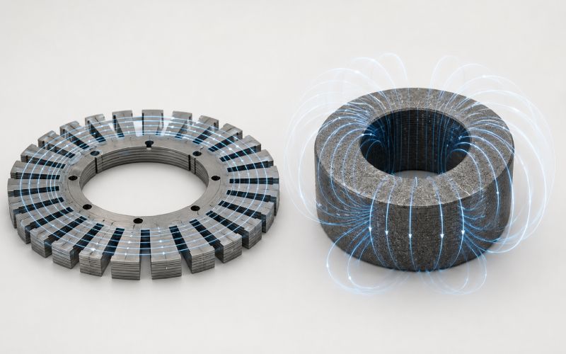
A laminated steel core is built from thin sheets of electrical steel. Each sheet is coated or insulated from the next. The stack carries magnetic flux, while the insulation breaks up eddy current loops through the thickness of the core.
Simple idea. Still powerful.
Lamination stacks work especially well when the magnetic flux path is mostly two-dimensional. In many radial-flux motors, transformer cores, generators, and solenoids, the flux mainly moves along the plane of each lamination. The material is being used in the direction it likes.
This is why laminated steel cores remain strong in:
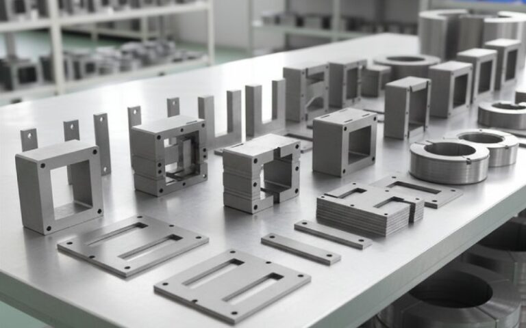
The strength of laminated steel is not just the material. It is the whole process.
Stamping. Stacking. Interlocking. Bonding. Welding. Annealing. Slot geometry. Lamination thickness. Coating quality. Burr control. Tooling maturity.
A good lamination stack is boring in the best way. It works.
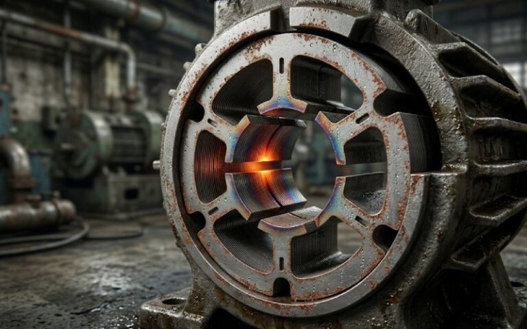
But there is a boundary. Once the flux wants to move out of plane, turn sharply, cross around compact 3D poles, or return through geometry that does not suit stacked sheets, laminated steel starts to need compromises.
Segments. Joints. Extra air gaps. More parts. Longer windings. Assembly tolerance problems.
That is usually where PM enters the conversation.
Powder metallurgy soft magnetic cores are made from magnetic powder particles that are electrically insulated from one another, compacted into shape, and heat treated.
The key difference is not only shape.
It is electrical path control.
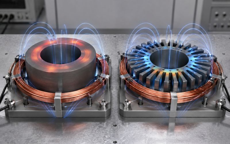
In laminated steel, eddy currents are controlled by stacking insulated sheets. In PM soft magnetic composites, eddy currents are restricted at the particle level. That can help when magnetic fields change quickly, when harmonics are strong, or when flux moves in several directions inside the same part.
PM also gives the designer more geometric freedom.
Instead of asking, “How do I slice this magnetic path into sheets?” the designer can ask, “Can I press this magnetic path as a compact 3D component?”
That shift matters.
Not always. But it matters in axial flux motors, transverse flux motors, claw pole rotors, compact actuators, high-speed machines, high-frequency inductive parts, and hybrid magnetic assemblies.
Still, PM brings a tax.
The relative magnetic permeability is usually much lower than good laminated electrical steel. Lower permeability can mean more magnetizing current. More current means more copper loss. And now the machine may run hotter even though the core loss looked better on paper.
That is the quiet trap.
PM can win the material comparison and lose the device comparison.
| Design factor | Laminated steel cores | PM soft magnetic cores | Practical meaning |
|---|---|---|---|
| Best flux path | Mostly 2D, in-plane | 3D, radial + axial + circumferential | PM makes sense when flux refuses to stay flat |
| Typical operating comfort zone | 50/60 Hz to several hundred Hz | Several hundred Hz to kHz-range designs | PM becomes more interesting as eddy current loss rises |
| Relative permeability range | Often thousands, depending on grade and field level | Often hundreds, sometimes lower or higher by formulation | PM may need more ampere-turns |
| Saturation flux density | Commonly around 1.7–2.0 T | Often around 1.4–1.8 T | Laminated steel usually carries more flux before saturation |
| Eddy current control | Thin insulated sheets | Insulated powder particles | PM can reduce local eddy current loops in 3D paths |
| Hysteresis loss | Often strong at low frequency | Can be higher because of particle deformation and processing | PM needs careful heat treatment and testing |
| Shape freedom | Limited by stamping and stacking | Better for compact 3D shapes | PM can reduce joints, parts, and winding length |
| Tooling cost | Stamping tooling, stacking tooling | Compaction tooling, die design, heat treatment setup | PM needs stable geometry and enough volume |
| Best fit | Conventional motors, transformers, generators | Axial flux, transverse flux, claw pole, compact actuators | Topology decides more than marketing claims |
| Main risk | Burrs, interlaminar shorts, stacking loss, assembly gaps | Low permeability, density gradients, thermal path, tooling limits | Both need process control |
These are typical engineering ranges, not final design values. Real values depend on composition, thickness, coating, compaction pressure, heat treatment, flux density, temperature, and waveform.
That last word matters: waveform.
A clean sinusoidal test can hide what a real inverter-fed motor does to the core.
This is the cleanest reason to use PM.
If the magnetic flux needs to move axially, radially, and circumferentially in the same component, a lamination stack may fight the design. Laminated steel wants the flux to stay mostly in the sheet plane. PM is more isotropic, so it can support magnetic paths that do not fit neatly into stacked sheets.
This is why PM deserves attention in:
A normal radial-flux stator does not automatically need PM.
A transverse flux motor might.
That difference is everything.
At 50/60 Hz, laminated steel is usually comfortable. At a few hundred hertz, laminated steel can still perform well, especially with thinner gauge material. At higher electrical frequencies, high pole counts, fast switching, or strong harmonic content, eddy current losses become harder to manage.
PM can help because the insulated particles restrict circulating current paths.
A rough screening view:
| Magnetic operating condition | Likely starting point | Why |
|---|---|---|
| 50/60 Hz transformer-style flux | Laminated steel | High permeability and low low-frequency loss usually win |
| 100–400 Hz motor core | Laminated steel first | Thin laminations may solve the problem |
| 400 Hz–1 kHz with high harmonics | Compare both | PM may reduce eddy currents, but copper loss must be checked |
| Above 1 kHz magnetic excitation | PM becomes stronger candidate | Eddy current control and geometry freedom matter more |
| Local high-frequency ripple on lower-frequency main flux | Test both under real waveform | The average frequency is not the whole story |
Do not choose PM only because the inverter switches fast.
The core does not always “see” the switching frequency directly. It sees the flux waveform that survives through winding inductance, control strategy, slotting, rotor motion, and geometry.
The wrong frequency assumption can make the wrong material look brilliant.
For about ten minutes.
This is the system-level reason PM can win.
A PM core might have worse magnetic permeability than laminated steel. But if its shape allows shorter end windings, larger slot fill, fewer joints, less leakage flux, or a cleaner return path, the whole motor may improve.
That is the part that matters.
A motor does not care whether heat came from iron loss or copper loss. Heat is heat. Torque is torque. Temperature rise is temperature rise.
So the PM question should be framed like this:
Does the PM geometry reduce total machine loss, size, mass, or assembly cost enough to justify lower permeability?
Not:
Does PM have lower eddy current loss in a sample ring?
A sample ring is not a motor.
Sometimes the drawing tells you the answer before the simulation does.
If the laminated solution needs several core segments, difficult stacking, secondary machining, weld control, insulation repair, tight assembly alignment, and extra magnetic joints, PM may become worth serious testing.
Near-net-shape pressing can reduce part count.
That does not mean it is free. Powder compaction has its own rules:
PM is not a shortcut. It is a different manufacturing language.
If the design speaks that language, PM can be strong.
If it does not, laminated steel may be the cleaner answer.
Laminated steel should stay the baseline when the magnetic design is already planar, efficient, and manufacturable.
Use lamination stacks first when:
This covers a lot of motors.
Especially conventional radial-flux stators.
A good lamination stack with the right electrical steel thickness can outperform PM because it has higher permeability, higher saturation capability, and mature loss behavior. PM may reduce eddy currents, yes. But if it needs more current to produce the same air-gap flux, copper loss can eat the gain.
No drama. Just math.
The table below is not a replacement for datasheets or prototype testing. It is a way to avoid bad first choices.
| Material family | Typical form | Typical thickness or structure | Better for | Watch out for |
|---|---|---|---|---|
| Standard non-oriented electrical steel | Laminations | 0.35–0.65 mm sheets | 50/60 Hz to moderate-frequency motors | Eddy current loss rises with frequency |
| Thin-gauge electrical steel | Laminations | 0.10–0.30 mm sheets | High-speed or higher-frequency motors | More expensive processing, handling, stacking |
| Fe-based soft magnetic composite | Pressed PM core | Insulated powder particles | 3D flux, compact shapes, medium/high-frequency effects | Lower permeability, density gradients |
| Fe-Si or alloyed powder composite | Pressed PM core | Insulated alloy powder | Better resistivity or loss tuning | Cost, compaction behavior, heat treatment sensitivity |
| Hybrid laminated + PM core | Mixed construction | Sheets plus pressed sections | Local 3D flux or complex return paths | Interface gaps, assembly tolerance, modeling complexity |
A simple rule:
If the core is mostly a flat magnetic highway, use laminations.
If the core is more like a compact magnetic junction, test PM.
PM discussions often focus on iron loss.
That is too narrow.
A PM soft magnetic core can reduce eddy current loss at higher frequency. But lower permeability may require stronger magnetizing force. Stronger magnetizing force usually means more current. More current raises copper loss.
So the real comparison is:
PM core loss reduction minus extra copper loss from lower permeability plus or minus geometry gains from shorter windings or fewer joints
That is the real equation.
A laminated core may lose more in the iron but need less current. A PM core may lose less in eddy currents but need more copper excitation. Either one can win.
You will not know from a single material chart.
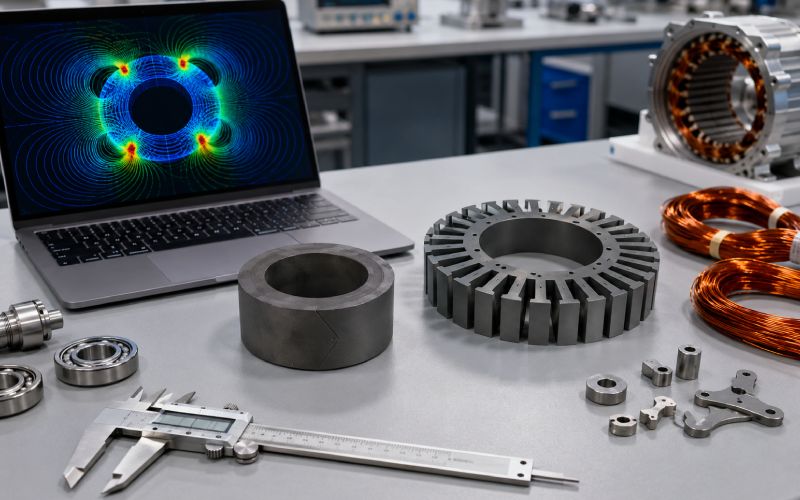
You need the full electromagnetic and thermal model.
Then you need a prototype.
Annoying, but true.
Cost is not just price per kilogram.
Laminated steel cost includes sheet material, coating, stamping, tool wear, scrap, stacking, bonding or welding, annealing when needed, inspection, and assembly.
PM cost includes powder, insulation treatment, blending, compaction tooling, press time, density control, heat treatment, finishing, coating, inspection, and scrap from cracked or out-of-density parts.
The cost question should be:
What does each option cost per finished magnetic function?
Not per kilogram.
Not per part in isolation.
A rough decision guide:
| Production situation | Laminated steel likely fit | PM likely fit |
|---|---|---|
| Prototype only | Easier to source or cut test stacks | Useful only if the PM shape is central to the concept |
| Low volume | Usually safer unless geometry is complex | Can work if it removes several parts or a hard assembly step |
| Medium volume | Strong if stamping tools are already justified | Stronger if compaction tooling is amortized and machining is low |
| High volume | Very strong for conventional stacks | Strong if the part is compact, repeatable, and near-net-shape |
| Frequent design changes | Laminations may be easier to revise by laser or wire-cut prototypes | PM tooling changes can be expensive |
| Complex 3D magnetic path | May need many pieces and joints | Often worth serious RFQ and prototype testing |
Be careful with fixed volume thresholds.
A tiny PM actuator and a large motor core do not share the same cost logic. A simple stamped lamination and a segmented, bonded, skewed, multi-part lamination stack do not share it either.
The right cost model includes:
If PM removes one simple lamination stack, it may lose.
If PM removes six parts, two fixtures, a long winding overhang, and a magnetic joint, it may win.
That is the honest cost story.
Use PM as a serious candidate when at least two of these are true:
Stay with laminated steel when most of these are true:
A blunt version:
Use laminated steel when the magnetic path is flat. Test PM when the magnetic path is spatial.
Not perfect. Useful enough.
This happens a lot.
A team takes a laminated stator shape, makes the same shape from PM, then expects better performance.
Usually, that wastes PM.
PM should be used to change the magnetic architecture, not just the material label. If the shape remains a 2D lamination shape, laminated steel often keeps its advantage.
Core loss is not the machine.
Compare:
A PM core can show lower eddy current loss and still make the motor less efficient.
That feels wrong until the copper loss shows up.
PM materials often need more magnetizing force. That means higher current for the same flux target, unless the geometry compensates.
This is why PM works best when shape freedom gives something back.
Shorter flux path. Less leakage. Shorter winding. Fewer joints. Better packaging.
Without one of those gains, lower permeability becomes hard to defend.
“High frequency” is not enough.
Ask which frequency matters:
The core may see several of these at once.
A clean 1 kHz material test does not describe every high-speed motor.
Lower eddy current loss does not automatically mean lower temperature.
PM density, insulation layers, binder system, coating, part thickness, and mounting method affect heat flow. A compact PM part can trap heat in places a laminated stack would spread it.
Thermal modeling should not be added after the electromagnetic design.
It belongs in the first comparison.
Axial flux motors often need compact magnetic paths and short axial return structures. PM can help form teeth, poles, or stator sections that are not easy to build from flat sheets.
PM is not always better in axial flux. But it is often worth modeling.
Transverse flux machines are one of the clearest PM candidates because their magnetic paths are often three-dimensional. Laminated solutions can become segmented and assembly-heavy.
If the design has flux moving around the winding rather than simply across a flat stator stack, PM deserves attention.
Claw-shaped poles are awkward for traditional lamination stacks. PM can form claw and pole features more naturally, with fewer separate magnetic pieces.
The benefit is not only electromagnetic. It can also be assembly simplification.
Small actuators often have limited packaging space and complex flux returns. PM may help integrate the magnetic path into fewer parts, especially when response speed or AC excitation matters.
For inductors, chokes, and compact magnetic components working at higher frequency, PM can reduce eddy current effects while allowing shaped magnetic paths.
The trade remains permeability and thermal behavior.
Always.
Sometimes the best answer is not PM or laminated steel.
It is both.
A laminated section can carry strong planar flux. A PM section can handle a 3D return path, local tooth feature, or complex end-region flux.
Hybrid cores are less tidy to describe. That does not make them weak.
Real machines often reward mixed solutions.
Before choosing PM over laminated steel, test both options under conditions close to the real device.
Use this checklist:
| Test item | Why it matters |
|---|---|
| Real current waveform | Sinusoidal testing can miss inverter harmonics |
| Full frequency spectrum | Core loss may come from minor loops and ripple |
| Flux density mapping | Local saturation can decide the winner |
| Temperature rise | Loss is only meaningful when heat can escape |
| Magnetizing current | PM may need more current for the same flux |
| Torque or force output | Material gain must become device gain |
| Winding resistance | Shorter windings may justify PM |
| Assembly gap sensitivity | Laminated segments and PM joints both create risk |
| Density and dimensional checks | PM properties depend on process control |
| Repeatability over samples | One good PM sample does not prove production stability |
A good prototype comparison should not ask, “Which core material has lower loss?”
It should ask, “Which complete device gives the required output at lower temperature, lower cost, or smaller size?”
That is the result worth trusting.
Here is the practical way to decide.
The design is conventional, planar, and already efficient.
That means ordinary radial flux, transformer-style flux, moderate frequency, high flux density, and no major assembly pain from the lamination stack.
Laminated steel is not old technology in that situation.
It is the right tool.
The design is compact, spatial, high-frequency, or assembly-constrained.
That means 3D flux, axial or transverse paths, claw poles, short winding opportunities, difficult laminated segmentation, or core loss driven by harmonics and ripple.
PM earns its place when geometry creates value.
Not when it is simply swapped into a lamination-shaped part.
One region wants high-permeability planar steel and another region wants 3D flux freedom.
Many machines are not pure textbook shapes. A mixed magnetic core can be more practical than forcing one material to do every job.
Laminated steel cores are made from stacked insulated sheets. PM soft magnetic cores are made from insulated magnetic powder particles pressed into shape. Laminated steel controls eddy currents between sheets. PM controls them at the particle level.
Only in certain designs. PM is better when the magnetic path is three-dimensional, compact, or high-frequency enough that eddy current control and shape freedom matter. Laminated steel is usually better for conventional planar flux paths.
Use PM when it gives a real design benefit: 3D flux paths, shorter end windings, fewer magnetic joints, reduced assembly, or better high-frequency loss behavior. Do not use PM just because it sounds more advanced.
It can be. PM becomes more attractive when the motor has high electrical frequency, strong harmonics, or local flux ripple that causes high eddy current loss in laminations. But lower permeability can increase current, so the full motor loss must be checked.
There is no single cutoff. Below a few hundred hertz, laminated steel often remains strong. From several hundred hertz into the kilohertz range, PM becomes more interesting, especially if the flux path is 3D or the waveform has strong harmonics.
Lower permeability means the core may need more magnetizing force to reach the same flux density. That can increase current and copper loss. If PM does not reduce winding length, leakage, or part count, this penalty can outweigh its eddy current benefit.
Sometimes, but it must prove itself. A standard radial-flux stator is usually well matched to lamination stacks. PM only makes sense if it improves the total design through geometry, high-frequency behavior, assembly reduction, or packaging.
PM is often worth evaluating in axial flux motors because the geometry can involve compact and multi-directional flux paths. Still, laminated or hybrid solutions may win depending on flux density, cooling, cost, and production method.
It can, but not automatically. PM may reduce cost if it removes parts, cuts assembly steps, reduces machining, or shortens windings. It may increase cost if tooling is expensive, volume is low, or the PM part does not simplify the design.
Test real waveform core loss, magnetizing current, copper loss, flux density, temperature rise, torque or force output, dimensional repeatability, and manufacturable density. The final decision should be based on complete device performance, not material data alone.