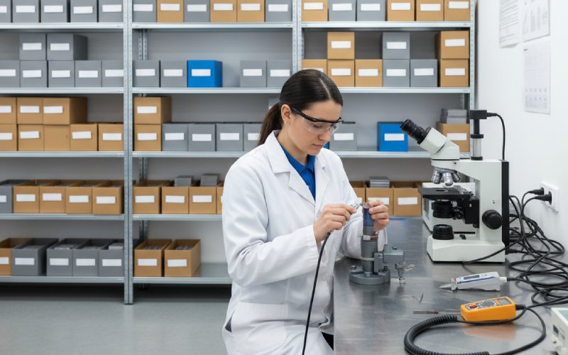
Lassen Sie Sino's Lamination Stacks Ihr Projekt verstärken!
Um Ihr Projekt zu beschleunigen, können Sie Lamination Stacks mit Details wie Toleranz, Material, Oberflächengüte, ob eine oxidierte Isolierung erforderlich ist oder nicht, Mengeund mehr.
Sie vertrauen bereits auf die Daten des CRGO-Werks: Sorte, Dicke, Kernverlust bei 1,7 T / 50 Hz, Polarisation.
Dann schneidet man sie. Dann ändern sich die Zahlen.
Schneiden, Fügen, Spannungsarmglühen und Stapeln verändern den Stahl in der Nähe der Kanten. Lokale Hysterese und Wirbelstromverluste nehmen um den Schnitt herum zu, so dass die reale Maschine fast immer höhere Eisenverluste aufweist als ein Modell, das von “idealem” Material ausgeht.
Zwei Mechanismen spielen eine Rolle für die Randbedingungen auf CRGO-Laminierungen:
In kontrollierten Tests schlossen künstliche Grate viele Lamellen haben einen kleinen Trafokern genommen und fast verdoppelt den Gesamtverlust bei hohem Fluss. Das ist keine subtile Optimierung. Das ist Ihre Garantie für Leerlaufverluste, die wegfällt.
Die Kantenbeschaffenheit ist also weniger ein “Feinbearbeitungsdetail” als vielmehr ein “versteckter Knopf zum Auf- oder Abwerten der Materialqualität”.”
Die meisten CRGO-Transformatorenkerne werden immer noch aus geschert oder gestanzt Bleche, nicht vollständig lasergeschnitten. Aus guten Gründen.
In der Nähe einer Scherkante zeigen sich unter EBSD und Nanoindentation mehrere Zonen: Überschlag, brünierte Scherung, Bruch und Grat. Jede dieser Zonen hat eine andere Härte und Versetzungsdichte als die Masse.
Unschönes Bild für CRGO:
Nichts davon wird im Kernverlustzertifikat des Walzwerks ausgewiesen. Das wird alles von Ihrer Schneide- und Stanzanlage hinzugefügt.
In Spezifikationen und Papieren finden Sie drei wiederkehrende Zahlen:
Sobald die Grate groß genug sind, um sich durch die anorganische Beschichtung zu fressen, bewegen wir uns von der “zusätzlichen Hysterese” in das Gebiet der “interlaminaren Kurzschlüsse”. Modelle und Experimente zeigen, dass diese Brücken die lokalen Wirbelstromverluste drastisch erhöhen können.
In einem klassischen Experiment mit künstlichen Graten an Kernen von Verteiltransformatoren wurden Gruppen von Blechen vollständig kurzgeschlossen:
Echte Kerne erreichen selten diesen schlimmsten Fall, aber die Richtung ist klar: Grathöhe × Gratkontinuität × Beschichtungsschaden = wie viel Ärger Sie sich eingehandelt haben.
Es ist schwer zu quantifizieren, aber einige Muster wiederholen sich immer wieder:
Wenn also aus einer “M**H”-CRGO-Platte ein zusammengesetzter Transformatorkern wird, ist die ursprüngliche W/kg-Zahl nur noch ein Ausgangspunkt. Die Randbedingungen entscheiden darüber, wie viel von diesem Vorteil erhalten bleibt.
Wenn auf Ihren Laminierungszeichnungen nur “CRGO M0H, 0,23 mm, zugeschnitten” steht, finanzieren Sie Experimente und kein Verfahren.
Typisch Punkte auf Vertragsebene die die Randbedingungen unter Kontrolle bringen:
Diese sind zwar langweilig zu verhandeln, aber viel billiger als ein 6-8% ohne Lastverlust, der nach dem Tanken entdeckt wurde.
“Laserschneiden = saubere, gratfreie Kanten, daher sollten die Verluste geringer sein.” Das klingt gut. Es ist aber nur halb wahr.
Es gibt wirklich zwei verschiedene Anwendungen von Lasern auf CRGO:
Die Physik und das Ergebnis sind überhaupt nicht dasselbe.
Anstelle eines Scherbandes erhalten Sie beim Laserschneiden ein wärmebeeinflusste Zone (HAZ):
Untersuchungen an Elektrostählen (meist nicht orientiert, aber die Mechanismen sind dieselben) zeigen durchweg:
In einer kürzlich durchgeführten experimentellen und Simulationsstudie führte die Berücksichtigung von Schnittverletzungen im Modell im Vergleich zu ihrer Nichtberücksichtigung zu Eisenverlusten von etwa 30% höher sobald ein realistischer Schnitt einbezogen wurde.
Detaillierte Verlustmessungen an Motoren, die aus lasergeschnittenen Blechen hergestellt wurden, zeigen in der Regel höhere magnetische Verluste als bei sorgfältig gestanzten Blechen, wenn Material und Geometrie konstant bleiben.
Laserkanten sind also geometrisch ordentlich, aber magnetisch betont.
Es kommt darauf an, wo man in diesem Dreieck steht:
Jüngste Arbeiten zu hochwertigem Elektroband zeigen:
Das kann man so sagen:
Für CRGO-Transformatorenkerne bei 1,7 T bei 50 Hz, der bisher sichersten praktischen Regel:
Bevorzugen Sie geschertes/gestanztes CRGO mit strenger Gratkontrolle und bewährter Kernverlustleistung. Verwenden Sie Laserschneiden für Prototypen, Sonderanfertigungen oder wenn die Geometrie Sie dazu zwingt, aber fragen Sie nach Daten, nicht nach Versprechungen.
Jetzt kommt der verwirrende Teil: Laseranreißen ist ebenfalls ein Laserverfahren, allerdings mit dem entgegengesetzten Ziel.
Anstatt Kanten zu schneiden, schreibt der Laser flache Linien in die Oberfläche und führt bewusst kleine Spannungsbereiche ein, um große Domänen zu unterteilen. Wenn die Parameter im Sweet Spot liegen, zeigt domänenveredeltes CRGO etwa 5-15% geringerer Kernverlust als die gleiche Sorte ohne Ritzen, im Bereich von 0,23-0,30 mm.
Zwei wichtige Vorbehalte für Käufer:
Ein vernünftiger Spekulationsstapel ist also:
Sehr ungefähre Angaben, gedacht als Orientierungshilfe für Entwurf und Kauf, kein Ersatz für eine Prüfung vor Ort.
| Artikel | Gut kontrollierte Scheren/Stanzen | Gut kontrollierte Laserschneiden |
|---|---|---|
| Wichtigster Schadensmechanismus | Plastische Verformung, Eigenspannung, Scherbänder in einem Bereich von ~0,2-0,5 mm vom Rand. | Thermischer Zyklus + HAZ; mikrostrukturelle Veränderungen, Zugspannungen, mögliche Recast-Schicht. |
| Risiko der Grathöhe | Mittel bis hoch, wenn die Werkzeuge stumpf werden oder der Abstand abweicht. Ziel ≤ 0,02-0,03 mm; >0,03 mm bereits riskant. | Sehr geringer sichtbarer Grat; die Kanten erscheinen “sauber”. Mikrograte sind immer noch möglich, aber normalerweise kleiner. |
| Art der Beschädigung der Beschichtung | Mechanische Abplatzungen und Faltenbildung am Rand, insbesondere bei großen Abständen. | Lokale Verbrennung oder Rissbildung der Oberflächenbeschichtung in der Nähe des Schnitts; hängt stark vom Prozessgas/der Leistung ab. |
| Risiko eines interlaminaren Kurzschlusses | Hoch, wenn Grate in die Beschichtung eindringen und kontinuierlich laufen; schwere Fehler können den Verlust bei hohem Fluss fast verdoppeln. | Weniger von Graten verursacht, aber immer noch möglich durch Spritzer oder Überbrückung von Gussresten. In der Regel weniger schwerwiegend als schlechte Scherung. |
| Typische Auswirkungen auf den Gesamtkernverlust (gegenüber idealem Material, Verteiltransformator, 50 Hz) | Bei guter Kontrolle: oft +5-15% über den Datenblattwerten; bei schlechter Gratkontrolle oder lokalen Kurzschlüssen kann er viel höher liegen. | Bei guter Kontrolle: immer noch oft schlechter als optimierte Scherung bei 1,0 T, manchmal vergleichbar bei höherem Fluss, wenn abgestimmt; +10-30% gegenüber dem Idealwert ist in Studien üblich. |
| Flexibilität der Geometrie | Erfordert Werkzeuge; teure Designänderungen; ideal für hohe Stückzahlen. | Werkzeuglos; einfache Designänderungen; ideal für Prototypen, Sonderanfertigungen und Kleinserien. |
| Beste Anwendungsfälle für CRGO | Großvolumige Leistungs- und Verteilertransformatorbleche; alles mit strikter Null-Last-Verlust-Garantie. | Prototypenkerne, Sonderformen oder wenn das Stanzen von Werkzeugen nicht gerechtfertigt ist und Sie den zusätzlichen Verlust tolerieren/prüfen können. |
Sie schließen einen Auftrag für eine Laminierung oder eine Ausschreibung für einen Transformator ab. Was schreiben Sie eigentlich?
Überlegen Sie, ob Sie die Klauseln nach diesem Muster aufbauen wollen (passen Sie die Zahlen an Ihre Standards an):
Damit wird “nice edge” zur vertraglichen Realität statt zu einem vagen Versprechen.
Wenn ein fertiger Transformator 5-10% einen höheren Leerlaufverlust aufweist als geplant:
Nicht jede Überschreitung ist ein Kantenproblem, aber es ist oft eine der billigsten Lösungen für die nächste Charge.
Nicht immer, aber in der Regel für klassische 50-Hz-Transformatorbedingungen. Die meisten Studien zeigen nach wie vor einen höheren spezifischen Eisenverlust für lasergeschnittene Proben als für gut gescherte Proben desselben Stahls, insbesondere um 1,0 T.
Wenn Ihr Lieferant in sehr streng kontrollierte Laserparameter investiert hat und Daten zum Stapelkernverlust vorlegen kann, die Ihren Spezifikationen entsprechen, können Sie dies akzeptieren. Ohne diese Daten ist das Scheren/Stanzen mit Gratkontrolle die sicherere Lösung.
Für CRGO im Bereich von 0,23-0,30 mm, 0,02-0,03 mm Die maximale Grathöhe ist ein realistischer Wert, auf den sich viele beziehen.
Darüber hinaus steigt das Risiko einer Durchdringung der Beschichtung und interlaminarer Kurzschlüsse schnell an. Und denken Sie daran, die durchgehende Gratlänge, Ein hoher, aber isolierter Grat ist weniger gefährlich als ein langer, leitfähiger Grat.
Das Spannungsarmglühen hilft, aber es stellt den Stahl nicht vollständig auf den Walzzustand zurück. Eine Überprüfung der Herstellungseffekte zeigt, dass selbst nach dem Glühen die lokalen Kanten oft höhere Verluste und veränderte Magnetisierungskurven im Vergleich zum Hauptteil aufweisen.
Betrachten Sie das Glühen als Schadensbegrenzung, nicht als magischen Radiergummi. Gutes Schneiden plus Glühen ist immer besser als schlechtes Schneiden plus Glühen.
Sie sind wichtig weniger, aber sie verschwinden nicht.
Bei niedrigem Fluss (z. B. unter 1,2 T) ist die zusätzliche Hysterese aufgrund von Kantenbeschädigungen bescheiden. Aber interlaminare Kurzschlüsse, die durch Grate verursacht werden, führen zu Wirbelströmen, die stärker mit der Frequenz und der Geometrie als mit der Flussdichte skalieren. Bei Tests mit künstlichen Graten wurden große Verlustzunahmen festgestellt, selbst wenn die durchschnittliche Flussdichte nicht extrem war, weil die lokalen Felder in der Nähe der Grate konzentriert waren.
Für Verteilertransformatoren, bei denen es zu Übererregungsereignissen kommen kann, ist es eine billige Versicherung, den Randbereich sauber zu halten.
Wenn Ihr Verlustbudget knapp bemessen ist oder Ihr Versorgungskunde Leerlaufverluste bestraft, kann domänenveredeltes CRGO den Aufpreis wert sein; eine Kernverlustreduzierung von 5-15% ist realistisch, wenn alles aufeinander abgestimmt ist.
Aber Sie sehen diesen Vorteil nur, wenn:
Grate bleiben unter Kontrolle
Beschichtung bleibt intakt
Das Schneiden und Stapeln verursacht nicht mehr Verluste als das Ritzen.
Also ja, extra bezahlen nur wenn der Laminierungslieferant auch nachweisen kann, dass er den Kanten- und Stapelprozess unter Kontrolle hat.
Es gibt keine allgemeingültige magische Zahl, aber ein praktikables Muster, das viele Pflanzen verwenden:
Für jede eingehende Spulenklasse/Dicke: 1 Epstein-Test von der Spule (eingehend)
1 Epstein- oder Ringprobe aus verarbeiteten Laminaten nach dem Schneiden/Glühen
Für montierte Kerne: 1 Leerlaufverlustprüfung pro Los oder pro Transformator-Bemessungsgruppe (z. B. 1 pro 50 Einheiten)
Forschungen zu gratinduzierten Fehlern legen nahe, dass einige wenige fehlerhafte Laminate den Gesamtverlust unverhältnismäßig stark beeinflussen können. Sie wollen also eine Probenahme, die eine Prozessabweichung erkennen kann früh, nicht nur, wenn ein großer Transformator bei der Werksprüfung versagt.