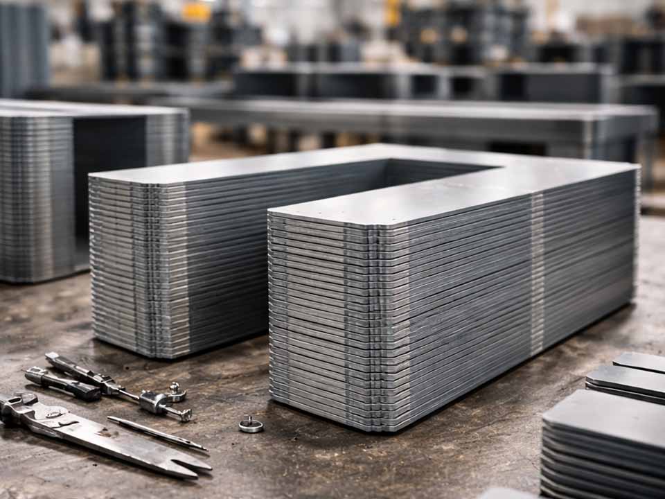
Let Sino's Lamination Stacks Empower Your Project!
To speed up your project, you can label Lamination Stacks with details such as tolerance, material, surface finish, whether or not oxidized insulation is required, quantity, and more.
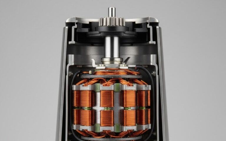
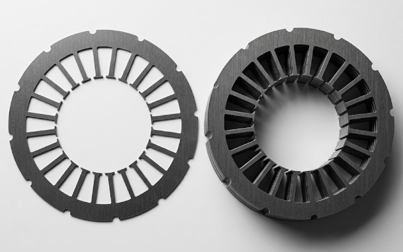
Lamination stacks are unforgiving. A stamped part can look clean on the bench and still behave badly once it becomes a rotor or stator pack. That is the real trap.
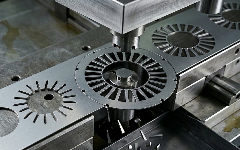
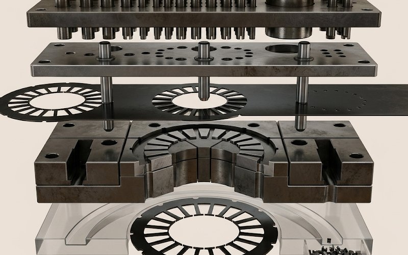
For motor laminations, die design is not just about holding the outer profile. It is about holding the profile and the cut edge and the registration from station to station. Those three drift together. Tight repeatability is needed because the lamination stack has to satisfy electrical, magnetic, and mechanical requirements at the same time. Mechanical cutting also changes magnetic behavior near the edge; published work shows higher iron loss, lower permeability, and stronger degradation as cutting-edge length per unit mass rises.
One note before the details. “Key tolerances” in this article means die-side process tolerances and control windows, not a fake universal print tolerance for every motor design. Exact part GD&T depends on diameter, slot count, power level, air-gap strategy, stack method, and inspection method. Still, the die itself has a short list of dimensions and process windows that deserve most of the attention. Those are the ones below.
The first reason is obvious enough: thin electrical steel does not give much forgiveness. The second reason is less obvious. Many of the most sensitive features in a motor are not big features. They are narrow ones. Slot openings. Tooth tips. Bridges. Small pilot holes. Little notches that look harmless on a strip layout and then decide whether the stack runs quietly or not.
That matters because stator inner diameter, slot dimensions, and related geometric tolerances influence air gap, winding volume, inductance, back EMF, torque ripple, and assembly fit. Recent slot-inspection research also shows that slot width, depth, lamination misalignment, and burr presence through the stack length are critical enough to justify dedicated noncontact inspection. So yes, a lamination die is a dimensional tool. It is also, quietly, an electromagnetic performance tool.
And then there is the cut edge. Burrs are not just cosmetic. Edge burrs can bridge adjacent sheets and create interlaminar fault paths. Published electrical-core work notes that edge burrs can lead to local heating, added eddy-current loss, winding-insulation damage, and in severe cases core failure.
Not every tolerance deserves the same energy. Some dimensions mostly affect fit. Others affect motor behavior, stack quality, and die stability all at once.
| Priority area | What really needs control | Why it matters in lamination stacks | What usually causes drift |
|---|---|---|---|
| Bore-to-OD and feature-to-feature position | Positional relationship, not just single dimensions | Changes air-gap behavior, fit, and stack alignment | Weak piloting, distorted pilot holes, uneven strip support |
| Slot opening, slot depth, tooth-tip profile | Narrow magnetic and winding-related geometry | Affects winding insertion, local flux path, torque ripple, and slot burr exposure | Poor station timing, strip movement after pilot engagement, punch wear |
| Punch-to-die clearance | Stable clearance over the regrind cycle | Controls burnish, fracture, burr trend, slug release, and punch wear | Clearance set once and never requalified after wear or sharpening |
| Pilot fit and pilot timing | Hole size, pilot nose size, and timing sequence | Final strip registration happens here, not at the feeder | Pilot too large, too short, too late, or working on a damaged locating hole |
| Slug evacuation path | Land, relief, drop path, and anti-pullback method | Keeps scrap out of the next hit and protects edge quality | Long land, sticky lubricant, over-entry, trapped vacuum, rough relief finish |
Those priorities line up with current metrology and manufacturing findings: rotor and stator laminations need high-repeatability dimensional control; slot geometry and burrs within the finished stack are inspection-critical; and cut-edge quality has direct electrical consequences.
This is where many lamination tools are won or lost. Not because clearance is glamorous. It is not. Because clearance quietly controls too many other things.
A long-used starting point in stamping is about 5% of stock thickness per side. That baseline still matters. But thin stock often does not behave well at that baseline. High-speed stamping references note that material thinner than 0.020 in. (0.5 mm) commonly needs substantially higher punch-to-matrix clearance before the pierced hole becomes larger than the punch point and the slug frees up in the matrix. Thin material can also need more clearance to offset bulging and compression around the punch.
That means the useful question is not “What is the correct clearance?” It is closer to this: At what clearance does this coated electrical steel give stable edge quality without turning slug control into a fight?
Here is a practical starting table.
| Die-side item | Practical starting window | Why it matters | What to check on the press |
|---|---|---|---|
| Punch-to-die clearance, per side | Start near 5% of stock thickness per side; move upward on thin gauges when slugs stay tight in the die or the hole closes on the punch | Edge quality, burr trend, tool life, slug freedom | Burnish/fracture balance, burr growth, hole size vs. punch size, slug jamming |
| Pilot-to-hole fit | Pilot point commonly 0.0005 to 0.0010 in. smaller than the locating hole | Final registration without sticking | Witness marks in the hole, peening, delayed pickup |
| Pilot timing | Pilot should enter and start locating before the stripper/pad clamps, often about 1–2× material thickness before pad contact | Prevents trying to move clamped stock | Station mismatch, side load, scuffing around locating holes |
| Punch over-entry | Keep to the minimum needed; in high-speed work, guidance often holds it to 0.020 in. (0.5 mm) max | Excess suction, wear, slug pullback | Heat tint near punch tip, pulled slugs, rising withdrawal force |
| Matrix land length | For thin-stock work, keep land from getting excessive; one common rule is not over 4× stock thickness | Long land traps or stacks slugs | Slug stacking, matrix packing, chipped tips |
These are starting windows, not promises. They come from current stamping guidance on perforating, piloting, and high-speed slug behavior. They work best when verified against actual strip samples, not just CAD intent.
There is also a counterintuitive point here. More clearance does not always mean more burr in the way people expect. Some perforating references report that a large increase in clearance can reduce burr height to a minimum and extend tool life, but only if slug control has been designed in. Without that second part, the same move can trade burr trouble for pullback trouble. So the die designer does not optimize clearance alone. Clearance and slug strategy have to be set together.
The feeder gets the strip close. The pilot finishes the job. That is still the cleanest way to think about it.
In progressive tooling, the pilot working length has to extend beyond the stripper so the pilot can pick up the hole and move the strip into position before other punches commit the next cut. Stamping guidance describes the pilot nose as entering the hole before stripper contact, with the pilot point often sized slightly under the hole to avoid sticking. Recent piloting guidance gives a typical fit of about 0.0005 to 0.001 in. to the pilot hole; older tooling references commonly size the pilot point 0.001 in. smaller than the punch that made the locating hole.
That sounds like a tiny detail. It is not. Late pilot entry causes a chain reaction:
The strip is not fully located. The pad clamps. Then the tool tries to cut, shave, or coin from a half-wrong position. By then the die is not correcting error anymore. It is hard-stamping the error into the part.
Thin laminations make this worse. Current thin-gauge production notes point out that what used to count as thin, around 0.014 in., now looks heavy next to 0.006 in. and 0.004 in. material. As the gauge drops, the strip gets less tolerant of long unsupported travel and more sensitive to support, feed stability, and pilot timing.
So for lamination dies, a good pilot strategy usually means five things:
Pilot from a clean, low-distortion feature.
Keep the pilot slightly under the hole, not “as tight as possible.”
Make the pilot engage before the pad fully traps the strip.
Avoid asking the same pilot hole to survive too much upstream abuse.
Recheck pilot fit after regrinds, not only after initial tryout.
Electrical-steel insulation coatings are not all doing the same job. Standard coating classifications distinguish different chemistries and intended functions, including insulation level, punchability, weldability, anneal resistance, and pressure resistance. Some coating classes are explicitly associated with improved punchability, while others are chosen for harsher thermal or pressure conditions.
So a clearance recipe that behaved well on one coated grade should not be copied blindly to another. Not even when the base thickness looks similar. Coating choice affects friction, surface damage sensitivity, and how much burr or edge roll the downstream stack can tolerate before insulation performance starts to fade. The die settings need to be frozen against the actual coated material, not against a material family name.
Slug control is not a housekeeping topic. It is a quality topic. A pulled slug can mark the next lamination, chip a tip, bruise a narrow tooth, disturb the coating, and start a burr trend that shows up much later in stack assembly. By then the real cause is already two shifts old.
High-speed stamping references identify several recurring causes of slug pulling: trapped vacuum, sticky lubricant, punch over-entry, and loose clearance with no retention method. The same references also show that withdrawal can account for a large share of punch wear, and that punch over-entry increases suction on withdrawal.
Three control layers matter most.
First, the punch face. Spring-loaded ejector pins or vented punches help break the vacuum seal and push the slug away from the punch face during withdrawal. For round punches, conical shear is also used because it lowers load and can reduce slug pull tendency.
Second, the die opening. Excessive land length is one of the main causes of slug jamming. Guidance for thin-stock work commonly keeps land length at no more than about four times material thickness, with taper or reverse-taper relief used to help slugs release cleanly. Smooth relief finish matters too; rough-drilled counterbores can catch slugs and promote tumbling.
Third, the drop path. Good die standards still say the obvious thing because it remains true: provide clearance holes through the die shoe for all slugs and pilot holes. Separate part drop from scrap drop wherever you can. Give scrap a clear path out, not a chance to loiter under the cutting zone.
One last detail. Burr control and slug control are linked. The older general stamping rule that burr height can be as high as 10% of sheet thickness is too loose to use as a comfort blanket for lamination stacks. In electrical laminations, burrs can create interlaminar shorts. Published electrical-core work cites examples around 0.05 mm over a 10 mm edge length, with higher local peaks sometimes treated separately, and some production guidance for lamination stacks flags burrs in the 10–20 μm range as already meaningful for piling quality. The sensible practice is to set your internal process alarm well below the old 10% rule and confirm the final limit against stack factor, insulation resistance, and thermal results.
When a lamination stack starts showing misalignment, rising burr, or random slot tightness, do not start at the finished part and guess. Walk backward.
Check the strip path.
Then check the locating hole condition.
Then pilot fit and timing.
Then punch-to-die clearance at the active station.
Then land and relief condition.
Then over-entry.
Then lubricant amount and where it is actually landing.
That order is not elegant. It works. Pilot-hole damage and strip instability often appear earlier than obvious part defects, and slug behavior can tell you whether the clearance problem is geometric, wear-related, or just being amplified by withdrawal and vacuum.
A common starting point is about 5% of stock thickness per side, but thin electrical steel often needs more than that before the hole stops gripping the punch and the slug drops cleanly. Treat 5% as a baseline, not a fixed answer.
A common practice is to size the pilot point about 0.0005 to 0.0010 in. smaller than the locating hole. Older tooling references often state 0.001 in. smaller than the punch that made the locating hole. The goal is controlled entry without sticking.
Before the stripper or pressure pad fully clamps the strip, and before other punches start critical work. One practical guideline is for the pilot to begin locating about 1–2× stock thickness before pad contact.
Usually because several things drift together: wear changes the real clearance, over-entry or land condition increases suction and drag, lubricant seals the vacuum pocket, and the slug path gets less clean. Slug pulling is rarely caused by one detail alone.
There is no honest universal number. The old general stamping rule of 10% of stock thickness is too broad for many lamination applications because burrs can create interlaminar shorts. For electrical laminations, the final limit should be tied to insulation integrity, stack factor, and heat rise, with internal process alarms set much lower than the general rule.
Yes. Standard coating classifications distinguish coatings by insulation level, punchability, weldability, and thermal resistance. That means the same thickness with a different coating system may not want the same clearance, burr alarm, or maintenance interval.
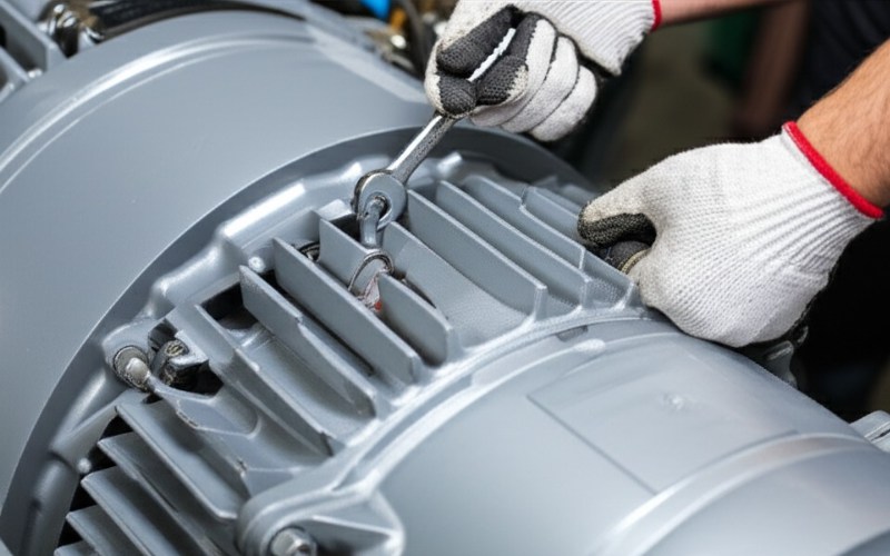
A motor lamination die does not fail all at once. It drifts. Clearance drifts. Pilot behavior drifts. Slug behavior drifts. Then stack quality follows.
The best tools are not the ones that make one sharp sample part. They are the ones that keep bore position, slot geometry, edge condition, and scrap evacuation stable over real run time. That means setting clearance as a live process window, giving pilots true locating authority, and treating slug control as part of part quality from the first layout review onward.