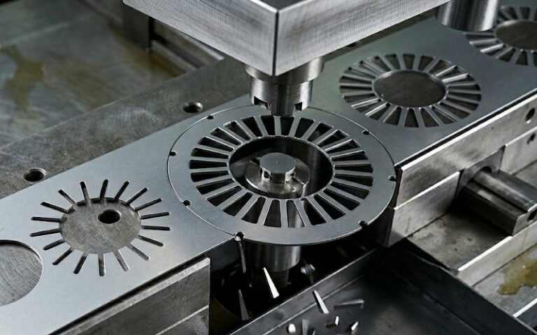
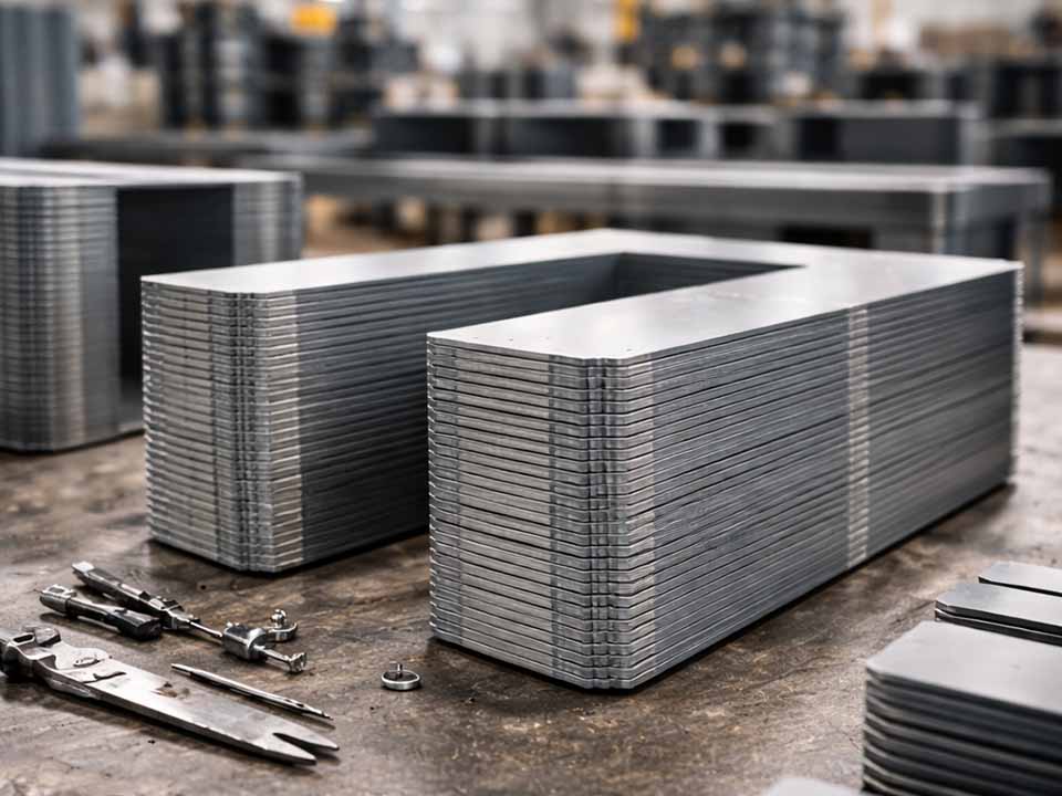
Let Sino's Lamination Stacks Empower Your Project!
To speed up your project, you can label Lamination Stacks with details such as tolerance, material, surface finish, whether or not oxidized insulation is required, quantity, and more.
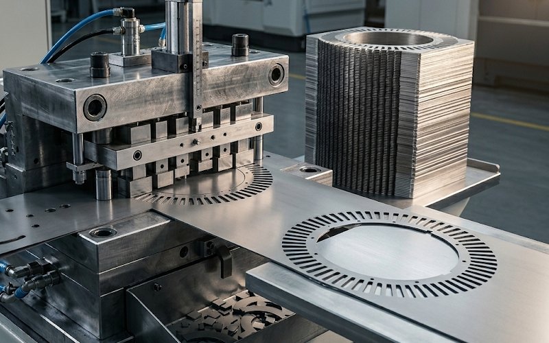
Thin electrical steel is used for one reason above the others: lower thickness helps cut high-frequency iron loss. In published motor data, moving from 0.35 mm to 0.30, 0.25, and 0.20 mm classes can reduce high-frequency iron loss by roughly 20% to 40%, depending on grade and test condition. That gain is real. It is also easy to give back in stamping if the die bruises the edge, lifts the strip, or lets narrow bridges buckle. Punching damage has been linked to higher core loss and measurable performance loss after cutting.
Thin electrical steel does not wrinkle because it is weak. Not exactly. It wrinkles because the die loses control of the strip at the wrong moment: before the cut, at breakthrough, or during withdrawal. So the design target is simple to say and harder to execute. Keep the strip flat. Keep it guided. Keep the release quiet.
A thin-lamination die is usually stable when it follows six rules:
That is the short version. The rest is where the die either works, or starts making expensive scrap.
In production, “wrinkling” is often a mixed symptom, not one clean failure mode. It can show up as:
The root causes are usually compressive stress, poor support, uneven release, or all three at once.
This gets more serious as thickness drops. In experimental work on thin silicon steel, buckling deformation was seen only at the lower sheet thickness, and the reported maximum buckling height reached about 164 μm under some cutting conditions. So once the sheet gets thin enough, flatness is no longer a secondary quality check. It becomes a primary die-design constraint.
There is another part designers sometimes underestimate: the cut edge affects more than the edge. Residual-stress studies on punched non-oriented electrical steel reported an affected zone around 0.4 to 0.5 mm from the edge. That is a big distance when the part contains narrow teeth, bridges, or slot corners. If the die damages those areas, the lamination may still pass dimensional inspection and still behave badly in stacking and magnetic performance.
For thin electrical steel, the die type should be chosen by asking one question first:
At what point does the strip become too weak to stay flat on its own?
That question usually leads to one of three directions.
Use a progressive layout when you need volume, repeatability, and controlled sequencing of internal features. This is often the best route for laminations with slots, windows, narrow teeth, and pilots, because you can keep more material connected while early stations build location and distribute strain.
Use this when concentricity and one-hit perimeter control matter more than feed progression. It can work well for simpler laminations, but for very thin stock the release event can be harsher because more cutting happens at once. That means higher demand on stripping and support.
Use this for development, edge studies, burr studies, and clearance trials. It is often the fastest way to find the real clearance window before locking a production layout.
A practical rule, maybe the most practical in this whole article: the thinner the sheet, the less you should trust a layout that removes too much support too early.
Most wrinkling problems in thin laminations start as layout problems.
A safer sequence usually looks like this:
The strip needs positive location before multiple punches are trying to share the load. Pilot engagement should happen before the main perforating punches enter. General stamping guidance makes the same point: pilots locate first, stripper holds second, cutting happens after that.
Slots, windows, and holes should generally be made while the strip still has full external support. Once the outer profile is mostly free, long internal cuts can turn a stable strip into a flexible frame. That is when bridges start to wave.
Do not punch a long, narrow slot in one station if that slot creates a weak ribbon of material beside it. Break it into two or three stations, or stage the ends and the center separately. The goal is not elegance. The goal is to avoid creating a long unsupported compression strip.
For thin stock, bridge placement matters more than bridge count. A narrow bridge placed beside a long slot is often worse than one fewer bridge placed next to a wider tooth root or yoke section.
This one is worth repeating. The outer profile is your last big source of stiffness. Spend it late.
For thin electrical steel, clearance is not just a burr setting. It affects edge damage, work hardening, residual stress, flatness, and magnetic loss.
Recent work on 0.50 mm non-oriented electrical steel found that as clearance increased, the depth and severity of the work-hardened layer increased and magnetic properties degraded. In that study, a lateral clearance of about 5% produced a complete and smooth shear section. Another study on punched non-oriented steel reported the most efficient iron-loss response after annealing at around 3% cutting clearance. Taken together, these results support a very practical starting point for thin laminations: begin trials at 3% to 5% of stock thickness per side, then adjust from actual results rather than habit.
What to look for during those trials:
Too little clearance can drive up force and wear. Too much clearance can make the release rough, deepen edge damage, and push the strip out of plane. A chart will not tell you where your material, coating, and station sequence cross that line. A controlled trial will.
For thin electrical steel, tool material does not usually decide wrinkling by itself. It affects wrinkling by controlling something just upstream of it: edge stability over time. As the punch and die wear, the effective clearance changes, the fracture zone shifts, the plastically affected layer grows, and the cut starts releasing less cleanly. Work on silicon-steel blanking has shown that tool wear can enlarge the zone of microhardness change and worsen the cut-edge condition as clearance drifts.
That is why tool material selection should be tied to production mode, not treated as a separate purchasing choice. Selection guidance for blanking and piercing tools places the main tradeoff where most die designers already feel it in practice: wear resistance versus toughness. High-wear cold-work grades are useful when edge retention is the main problem. Tougher cold-work grades are safer when narrow punches or breakthrough shock raise the risk of chipping. Powder-metallurgy cold-work steels are often chosen when both wear resistance and toughness matter at the same time, and carbide-based inserts are commonly reserved for very high wear situations where edge life dominates the decision.
The useful rule here is simple. Do not choose the hardest tool material by default. Choose the material that keeps a clean edge, resists chipping in your geometry, and holds the real running clearance inside the process window for as long as possible. That is the version of “tool material selection” that actually belongs in a wrinkling discussion.
For very thin electrical steel, the stripper is not a side component. It is the part of the die that decides whether the strip behaves like sheet or like foil.
Published stamping guidance is clear on two points:
That does not mean “use maximum pressure.” It means this:
A rigid stripper face supports the stock and limits local lift. Soft faces can deform, move laterally, and interfere with venting around the punch. That is a bad mix for thin laminations.
Uneven stripping pressure will print itself into the part. You may see one corner rise first, one bridge bow, one tooth twist. The fix is usually not more force. It is better support and a flatter pressure map.
Too much travel can over-compress springs, damage screws, and create interference near punch radii. It also makes the working cycle less stable.
Air has to go somewhere. Poor venting can contribute to slug pulling, irregular bulging, and unstable release. Thin stock notices these small things.
A lamination can be flat during entry and still leave the station distorted because breakthrough was too violent.
That is where punch sequencing matters.
Standard stamping practice recommends staggering punch lengths to reduce impact and snap-through shock. One useful detail from tooling guidance is often missed: using stagger equal to, or slightly less than, the burnish length can work better than simply matching stock thickness, especially in faster production. The idea is to let one punch group engage before the previous group fully snaps through, so the release energy is shared instead of dumped.
In thin electrical steel dies, that usually means:
Quiet release. Boring release. That is what you want.
Not all lamination geometry fails the same way.
The danger is side bending and local edge damage. Keep support close to the tooth root and avoid making the final side cuts in the same instant if that leaves the tooth free to flick sideways.
The danger is a ribbon of weak stock beside the slot. Split the slot, add nearby support, or change sequence so the strip is not asked to carry compressive stress through a long free edge.
The danger is buckling during withdrawal, not always during cutting. If the bridge looks fine at bottom dead center and fails after the ram rises, the problem is often stripping, venting, or release timing.
The danger is frame collapse. Delay the final blank as long as you can, and maintain carrier support in the stiffest zones.
A worn edge does more than grow burr. It changes fracture behavior, increases release instability, and makes the die compensate in ugly ways. In electrical steel, edge degradation also feeds directly into stack quality and magnetic behavior. Review literature on cutting damage shows that punching-induced edge effects can increase losses and degrade performance, while studies comparing cutting methods keep pointing back to residual stress, edge hardness, and burr as the critical quality indicators.
So do not wait for a visible disaster.
Set regrind triggers around:
That is a much cheaper way to run.
| Design item | Starting point | If too low / too tight | If too high / too loose | What to check first |
|---|---|---|---|---|
| Cutting clearance | 3%–5% per side | high force, rapid wear, galling risk | rougher fracture zone, more edge damage, flatness drift | burr, burnish, flatness, force |
| Stripper force | 8%–25% of perforating force as a design range; many jobs stay under 10% | strip lift, hanging on punches, poor location | marking, local distortion, wasted load | lift marks, withdrawal stability |
| Punch engagement | 2–3 stagger groups on larger punch sets | concentrated snap-through shock | unnecessary timing complexity | sound, load, distortion pattern |
| Outer profile timing | Late station | weak strip too early | none, usually safer late | frame stability |
| Long slot strategy | Split across stations | — | over-processing if split too much | waviness beside slot |
| Bridge design | Short, close to stiff zones | weak feed support | material waste | local buckle, twist |
| Regrind rule | By burr trend | premature maintenance | unstable edge quality if delayed | burr growth and stack drift |
The exact numbers still need trial confirmation. But this table is a better place to start than a generic clearance chart and a guess.
The strip loses stiffness and every later station becomes harder to control.
What matters is contact pattern and timing, not just force.
Thin stock does not forgive this.
The slot looks efficient on paper. The strip may not agree.
By the time burr is obvious, flatness has usually been drifting already.
That often hides the real issue for a while, then makes wear worse.
A good starting trial window is 3% to 5% of stock thickness per side. Use that as a process window, not a final answer. Then validate with burr, flatness, edge quality, and force data. Published studies on non-oriented electrical steel support this range as a sensible start, with 5% giving a smooth section in one study and 3% giving the best post-anneal loss response in another.
In most cases, yes. A spring stripper gives rigid support, holds the strip flat during perforating, and helps prevent the material from lifting or hanging on the punches during withdrawal. That combination is exactly what thin electrical steel needs.
Because the problem is often in withdrawal, not entry. Release shock, strip lift, poor venting, or uneven stripping pressure can distort a part that looked stable at bottom dead center.
Both. Burr reduces stack quality and can change effective stack height, while cutting damage near the edge can also increase loss and reduce machine performance.
No. Annealing may reduce some punching-induced stress effects, but it does not fix poor strip support, bad station order, weak bridges, or unstable release. If the die is making the strip move when it should not, that problem starts in tooling.
Usually this order works:
check stripper contact and pressure distribution
review station sequence around long slots and outer blank timing
run a narrow clearance trial
stagger punches that break through together
tighten regrind limits
A good thin-lamination die does not rely on force to keep parts flat. It relies on sequence, support, and controlled release.
That is the design logic: