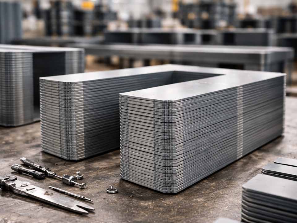
Let Sino's Lamination Stacks Empower Your Project!
To speed up your project, you can label Lamination Stacks with details such as tolerance, material, surface finish, whether or not oxidized insulation is required, quantity, and more.
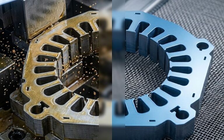
Lamination stack flatness describes how much the end face or functional surface of a stacked lamination assembly deviates from a true plane.
In GD&T practice, flatness is controlled by a tolerance zone made of two parallel planes. The surface must fit between those planes. Simple enough on paper.
A lamination stack makes it less simple.
One stamped sheet may show a slight wave. Another may have a small burr. Another may carry coil set from the strip. Add coating variation, joining pressure, fixture wear, and handling marks, then compress everything into a motor stator, rotor core, transformer core, or electrical steel stack. The final part may pass a height check and still fail during assembly.
That is why flatness should not be treated as a drawing decoration. It is a practical assembly condition.
The real question is not only:
Is the stack flat?
The better question is:
Does the stack seat, clamp, locate, and stay stable under the same condition it will see in production?
Flatness controls contact. Contact controls load. Load controls how the stack behaves when another part touches it.
A lamination stack may need to sit against an end plate, enter a housing, support a winding process, locate around a shaft, hold a magnetic air gap, or stay stable during bonding, welding, riveting, or interlocking. Poor flatness can disturb all of that.
Common assembly risks include:
Flatness problems often arrive under another name. Someone may say the stator is hard to insert. Someone else says the rotor stack height is drifting. A technician may report that a transformer core does not seat cleanly. Quality may only see “variation.”
The source may still be flatness.
Not always. But often enough to check early.
These three terms get mixed together. They should not.
| Feature | What it controls | Why it matters in lamination stacks |
|---|---|---|
| Stack height | Distance between two end faces | Affects package size, compression, housing fit, and build height |
| Flatness | Form of one surface | Affects seating, local contact, clamp load, and rocking |
| Parallelism | Orientation of one surface to a datum | Affects alignment, squareness, rotor/stator positioning, and assembly fit |
| Total indicated runout | Combined variation during rotation around a datum axis | Useful for rotating parts where face or OD variation affects balance or clearance |
| Perpendicularity | Squareness of a surface or axis to a datum | Important when the stack face must align to a shaft, bore, or housing datum |
A stack can have the correct height but poor flatness. It can be flat but not parallel to the opposite face. It can be parallel but still have local burrs that damage seating. It can look acceptable before joining and move after welding or curing.
That is the awkward part. But it is also where better inspection starts.
Flatness is not equally critical in every lamination stack. The priority depends on what the stack touches and how it is loaded.
| Application area | Why flatness matters | Main inspection focus |
|---|---|---|
| Motor stator lamination stack | Housing insertion, winding clearance, end-face seating, magnetic air gap stability | End-face flatness, OD condition, stack height under load |
| Rotor lamination stack | Shaft fit, balance, end-face squareness, magnet pocket consistency | Face flatness, bore alignment, parallelism, runout |
| EV motor core assembly | Tight packaging, high-speed performance, heat and vibration sensitivity | Flatness after joining, bore/OD relationship, loaded stack height |
| Transformer core laminations | Core build height, joint gap, clamp pressure, noise control | Layer seating, core face condition, joint region contact |
| Bonded lamination stack | Adhesive thickness control, cure distortion, final face stability | Pre-cure and post-cure flatness comparison |
| Welded lamination stack | Local heat distortion and pull near weld zones | Pre-weld vs. post-weld surface map |
| Interlocked lamination stack | Local deformation around lock points | Flatness near interlock zones and full-face seating |
The mistake is using one flatness rule for every stack. A large transformer core and a precision rotor stack do not have the same risk profile. Even two motor stacks can need different controls depending on diameter, stack height, lamination thickness, joining method, and final assembly load.
Stack height is easy to measure. That is why it gets measured often.
But height does not tell the full story.
Imagine a lamination stack that measures within height tolerance at three points. It may still have:
The stack height looks fine because the average distance is acceptable. The mating part does not care about the average. It touches the high spots first.
Then the clamp load follows the high spots. The housing sees a harder insertion. The fixture reads the part as tilted. The winding process loses clearance in one zone. The assembly team adjusts pressure, and the problem becomes less visible but not gone.
That is how flatness hides inside a height problem.
A thin lamination or stacked core can behave differently depending on how it is supported.
That is why the measurement condition must be defined.
The stack is measured without intentional external pressure.
Use this when:
Free-state measurement shows the natural shape of the stack. It can also exaggerate issues that disappear under real assembly load. That is not good or bad. It is just a different condition.
The stack rests on a reference surface, usually under its own weight or a light seating condition.
Use this when:
This is often more realistic than free-state measurement for thin stacks, but the seating method must still be written down.
The stack is measured under a defined load or clamping condition.
Use this when:
Loaded flatness is useful, but only if the load is controlled. “Press it down by hand” is not a measurement method. It is a habit.
The stack is measured after bonding, welding, riveting, interlocking, curing, heat exposure, or final compression.
Use this when:
For many production problems, this is the missing measurement. The stack passed before joining. Then the process changed it.
The exact method depends on tolerance, part size, production volume, and risk. Still, a useful inspection routine should look something like this.
Do not start with the whole part. Start with the assembly interface.
Ask:
Measure the surface that affects the failure mode. Measuring the wrong face very precisely does not help.
This sounds too basic. It is not.
A small chip between layers or under the stack can look like geometry error. Oil film, coating flakes, slivers, burr debris, and dust can all change contact.
Before measuring:
Many false flatness problems are actually cleanliness problems. Many real flatness problems are made worse by cleanliness problems.
Both matter.
Place the lamination stack on the defined support.
Record whether it rocks. Record where it contacts first. Record if light finger pressure changes the reading.
This first check gives useful clues. A stack that rocks on three points may have twist or a burr high spot. A stack that dishes upward may have residual stress, coating variation, or joining distortion. A stack that changes shape easily may need loaded inspection, not only free-state inspection.
If the stack is used under compression, repeat the measurement under a defined load.
The load should be chosen from the assembly condition, not guessed. For early process development, teams often compare several load levels to see how the stack compresses and whether flatness stabilizes.
Record:
If the flatness improves dramatically under light load, the stack may be wavy but compliant. If it remains poor under realistic load, the issue is more likely built into the stack: burrs, uneven joining, layer shift, coating variation, or fixture-induced distortion.
A single flatness value tells you how bad the surface is. It does not tell you why.
Use a point map.
For round motor stator or rotor stacks, include:
For rectangular or transformer core stacks, include:
A simple 9-point or 13-point map is often enough for early troubleshooting. More points may be needed for tight tolerance work or complex stack geometry.
Measure at least two states:
For bonded stacks, also measure after curing. For welded stacks, measure after cooling. For interlocked or riveted stacks, measure after the locking operation. For press-fit assemblies, measure before and after insertion if possible.
The difference between these states is often more useful than the absolute number.
If the stack is flat before welding and distorted after welding, the joining sequence needs attention. If it is poor before joining, do not blame the weld yet.
Inspection should not end with “pass” or “fail.”
Link flatness data to:
This is how a tolerance becomes real. Otherwise, it is just a number.
Different methods answer different questions. Use the method that matches the risk.
| Method | Best use | Strength | Watch-outs |
|---|---|---|---|
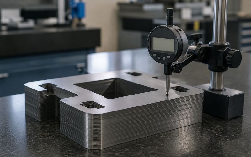
| Granite plate and indicator | Shop-floor checks, setup approval, quick troubleshooting | Simple, low cost, easy to repeat when controlled | Support condition and operator pressure can change results |
| Height gauge point map | Practical surface mapping | Shows crown, twist, edge lift, or local high spots | Requires enough points to avoid missing local defects |
| Coordinate measurement | Tight tolerances, complex datum relationships | Can connect flatness with position, parallelism, and bore/OD geometry | Point strategy and fixturing must match the part behavior |
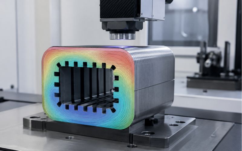
| Optical measurement | Thin parts, delicate surfaces, high data density | Non-contact, useful for fine surface behavior | Reflectivity, coating, filters, and burr spikes need control |
| Laser displacement scanning | Automated or semi-automated surface profiling | Fast mapping and trend monitoring | Needs stable fixturing and clear rules for outlier handling |
| Fixture-based loaded check | Assembly-relevant verification | Measures the stack in a condition closer to use | Fixture wear and load distribution must be monitored |
| In-process height and seating sensors | High-volume stacking control | Catches issues before final inspection | Does not replace full flatness mapping during development |
No method is automatically superior. A basic indicator check with a controlled load can be more useful than a high-end scan done under the wrong support condition.
A flatness number without context can create arguments. Add the context.
| Record item | Why it matters |
|---|---|
| Stack type | Stator, rotor, transformer core, bonded stack, welded stack, interlocked stack |
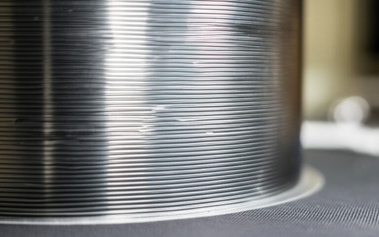
| Material condition | Electrical steel strip thickness, coating type, lot, and handling condition |
| Process stage | Loose stack, compressed stack, post-weld, post-cure, post-insertion |
| Surface measured | Top face, bottom face, assembly face, datum face, local land |
| Orientation | Burr-up, burr-down, flipped, rotated, indexed, skewed |
| Support method | Full plate, three-point support, fixture nest, inspection tool |
| Load condition | Free-state, seated, defined load, process clamp, final assembly load |
| Load value and contact area | Needed for repeatable loaded flatness checks |
| Measurement method | Indicator, height map, CMM, optical, laser, fixture gauge |
| Point map or scan path | Shows the shape pattern, not only the worst value |
| Cleaning condition | Prevents debris from being mistaken for flatness error |
| Fixture ID | Helps detect fixture wear or nest damage |
| Assembly result | Insertion force, rocking, clamp behavior, gap, runout, final test result |
This looks like extra paperwork until a flatness issue appears. Then it becomes the shortest path to the cause.
Flatness problems usually come from a chain of small errors. One issue starts it. Another makes it visible.
Burrs are small, but stacks multiply them.
If burrs align in the same direction through many layers, they can create artificial stack height, local tilt, pressure ridges, and uneven layer contact.
Burr problems are not only about burr height. Location and direction matter.
Check:
A burr that looks harmless on one lamination may become a spacer inside the finished core.
Electrical steel strip can retain stress from rolling, slitting, leveling, and handling. Stamping releases or redistributes some of that stress.
Thin features move more easily. Slot bridges, teeth, narrow webs, and small tabs may not relax the same way as the main body.
The result can be:
This is why individual lamination checks do not always predict stack behavior perfectly.
Insulating coating is necessary, but it adds thickness. If the coating is uneven, the stack may develop local high regions. Under compression, those regions carry more load.
Watch coating effects when:
Coating is part of the geometry, even when the drawing focuses on metal.
A stack is built layer by layer. Small shifts accumulate.
Alignment problems may come from:
If the stack face is not flat and the holes or slots are also drifting, the problem may be alignment rather than only surface form.
Welding, bonding, riveting, interlocking, and curing can all move the stack.
Typical patterns include:
Measure before and after joining. It removes guessing.
Fixtures are supposed to reveal part variation. Sometimes they create it.
Check:
A damaged fixture can make good stacks look bad. It can also force bad stacks into a temporary shape that later relaxes.
Thin laminations and stacked cores can be bent, dented, or locally damaged before anyone notices.
Risk areas include:
Flatness control starts before inspection. Storage trays, handling rules, cleaning, and transport all matter.
Do not start by tightening the tolerance. Start by finding what creates the shape.
The best improvement question is:
What exactly is failing during assembly?
Examples:
Each symptom points to a different control plan.
Flatness error has shape. Shape gives clues.
| Surface pattern | Likely causes | First checks |
|---|---|---|
| Center crown | Coating build-up, compression behavior, residual stress, joining pressure | Loaded vs. free-state flatness, coating thickness, clamp pattern |
| Edge lift | Burr direction, heat distortion, strip memory, fixture support | Burr map, pre/post joining measurement, support method |
| Twist | Uneven stacking, fixture wear, handling damage, uneven clamping | Contact pattern, fixture condition, layer alignment |
| Local high spot | Debris, burr cluster, dent, rivet/interlock distortion | Cleaning, visual inspection, burr height, local section check |
| Weld-side pull | Heat input, weld sequence, clamp imbalance | Pre-weld vs. post-weld map, weld location pattern |
| Post-cure bow | Adhesive shrinkage, uneven cure pressure, thermal mismatch | Pre-cure flatness, adhesive distribution, cure fixture check |
| Random variation | Material lot, handling, inconsistent seating, operator method | Process records, load condition, measurement repeatability |
Do not treat all flatness failures the same. A crown and a twist are not the same problem.
Burr control should include more than a maximum burr height.
Improve control by checking:
The goal is not only “smaller burrs.” The goal is fewer burr-driven gaps and pressure points inside the stack.
The stack should not wait until final assembly to become seated.
Possible controls include:
If the stack height suddenly changes during stacking, stop and inspect. Something changed: debris, flipped layer, burr build-up, alignment shift, or incomplete seating.
Do not mix these two issues.
Thickness variation changes stack height. Flatness variation changes surface form. Both can happen together, but they are not the same defect.
A useful investigation compares:
This prevents the wrong corrective action. Sorting material may help height variation. It may do little for burr-driven twist.
If flatness gets worse after joining, the joining process needs review.
For welded stacks:
For bonded stacks:
For riveted or interlocked stacks:
Joining should hold the stack together. It should not become the main source of distortion.
Fixture checks should be part of flatness control.
Set a schedule to inspect:
When one station produces more flatness failures than others, suspect the station before blaming the entire process.
There is no universal flatness tolerance for all lamination stacks. A tolerance copied from another design can be too loose, too tight, or simply irrelevant.
Use the assembly function to set the limit.
The tolerance should answer a production question:
At what flatness condition does this stack stop assembling correctly?
Not:
What number looks strict on the drawing?
| Assembly condition | Flatness control priority | What to validate before setting the limit |
|---|---|---|
| Press-fit stator stack | End-face seating and OD alignment | Insertion force, housing contact, stack tilt, winding clearance |
| Rotor stack on shaft | Face squareness, bore alignment, balance behavior | Shaft fit, face runout, bore relationship, rotational stability |
| Transformer core assembly | Layer seating and joint contact | Build height, joint gap, clamp pressure, noise behavior |
| Bonded stack | Pre-cure seating and post-cure stability | Adhesive layer control, cure distortion, final face condition |
| Welded stack | Distortion near weld zones | Pre-weld and post-weld maps, local pull, clamp sequence |
| Interlocked stack | Local deformation at lock points | Lock area height, full-face seating, stack height repeatability |
| Thin precision electrical steel stack | Compliance under light load | Free-state vs. loaded flatness, handling sensitivity, fixture method |
A tight flatness tolerance is useful only when it protects assembly. Otherwise, it can raise cost without reducing failure.
For production launch or recurring assembly trouble, use a layered control plan.
| Process stage | What to check | Why it matters |
|---|---|---|
| Incoming strip or lamination lot | Thickness, coating condition, visible wave, edge condition | Finds material-related variation early |
| After stamping | Burr height, burr direction, distortion, critical feature condition | Prevents bad layers from entering the stack |
| During stacking | Layer count, orientation, seating, height trend | Catches debris, flipped layers, and incomplete seating |
| Loose full stack | Free-state flatness, contact pattern, rocking | Shows natural stack behavior |
| Compressed stack | Loaded flatness, compressed height | Simulates assembly pressure |
| After joining | Flatness map, local distortion, height change | Identifies weld, bond, rivet, or interlock effects |
| Before final assembly | Assembly-face flatness, datum relationship | Confirms the stack will locate correctly |
| After final assembly | Fit, runout, insertion force, gap, performance output | Validates whether the tolerance actually works |
Not every stage needs full inspection forever. During process development, this plan helps locate the cause. In stable production, some checks can become periodic audits.
Watch for these signs:
Flatness is not always the root cause. But these symptoms justify checking it.
Use this sequence when the line is already seeing fit or seating problems.
Take several good stacks and several bad stacks. Measure them using the same method.
Compare:
Do not rely on one failed part. One part can mislead.
Check the stack at multiple stages:
The first stage where the flatness pattern appears is usually close to the source.
A repeatable shape is a clue.
Same high side every time? Check fixture, weld sequence, burr orientation, material feed direction. Random high spots? Check debris, handling, inconsistent seating. Distortion after cure? Check adhesive and cure fixture. Distortion after pressing? Check load path and parallelism.
Do not adjust everything at once.
Useful single-variable trials include:
One clean test beats five guesses.
After changing the process, do not celebrate only because flatness improved. Confirm the assembly problem improved too.
Check:
Flatness improvement is only valuable when the assembly result improves.
A drawing that says only “flatness” may not be enough.
A better specification should clarify:
This prevents a common argument:
Quality says the stack passes. Assembly says it fails. Both may be right if they are using different conditions.
Write the condition. Save the argument.
Height matters, but it does not describe the shape of the end face.
Add flatness or loaded seating checks when assembly contact matters.
Free-state data may not predict loaded behavior. Loaded data may hide handling problems.
Measure the condition that matches the failure.
Burr height alone is not enough. Direction and stacking pattern can create pressure ridges.
By then, the defect may be locked in.
Measure earlier during process development.
A tighter number can increase cost and inspection time without fixing the actual cause.
Tie the tolerance to assembly performance.
Fixtures wear. They collect debris. They bend. They create false patterns.
Inspect the inspection method.
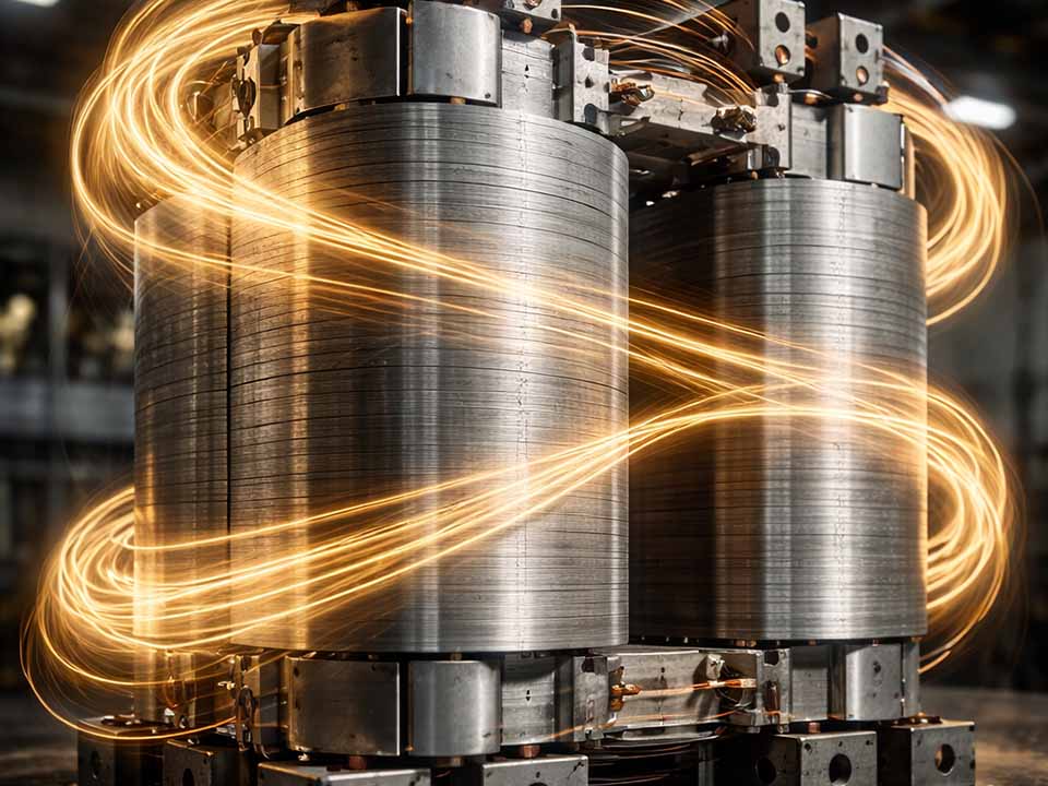
Lamination stack flatness is the amount of surface variation on a stacked lamination face compared with an ideal plane. In practical assembly terms, it shows whether the stack can seat evenly, clamp consistently, and maintain correct geometry during the next operation.
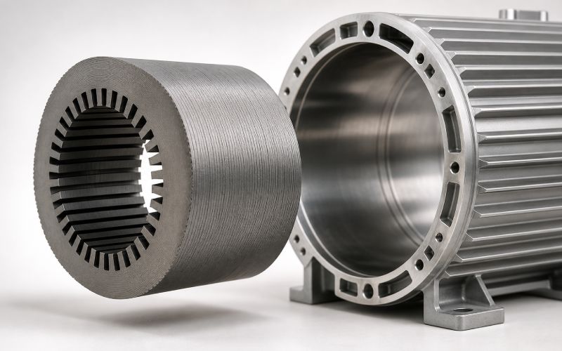
In a motor stator stack, poor flatness can affect housing insertion, end-face seating, winding clearance, stack height repeatability, and magnetic air gap stability. A stator may pass a basic height check but still create assembly force or alignment problems if the end face is crowned, tilted, or locally high.
Rotor lamination stack flatness can affect shaft fit, face runout, balance behavior, magnet pocket consistency, and end-face squareness. Small face errors can become more important in high-speed or tightly packaged motor assemblies.
No. Stack height measures distance between faces. Flatness measures the shape of one surface. A stack can meet height requirements and still fail assembly because the mating part contacts a high spot, burr ridge, crown, twist, or tilted face.
It depends on the assembly condition. Use free-state measurement when natural seating and handling matter. Use loaded flatness when the stack functions under clamp force or assembly pressure. For troubleshooting, measure both and compare the difference.
Loaded flatness is flatness measured while the stack is under a defined force or clamping condition. It is useful when the real assembly compresses the stack. The load value, contact area, support method, and dwell time should be recorded.
Common causes include burr build-up, residual stress, coating thickness variation, poor stacking alignment, debris, fixture wear, joining distortion, uneven clamping, and handling damage.
Burrs can act as small spacers between layers. When repeated across many laminations, they can create local high spots, tilt, uneven stack height, layer gaps, and poor seating. Burr direction and location are as important as burr height.
For basic checks, use a reference plate and indicator with a defined support condition. For better troubleshooting, use a mapped point pattern. For tighter or more complex parts, use coordinate measurement, optical measurement, laser scanning, or fixture-based loaded inspection.
Use enough points to reveal the surface pattern. For early troubleshooting, a 9-point or 13-point map is often more useful than three isolated readings. For round stacks, include ID, OD, center or hub regions, and areas near welds, rivets, interlocks, slots, or teeth.
Improve flatness by controlling burrs, cleaning layers and fixtures, improving stacking alignment, defining seating force, monitoring stack height under load, checking fixture wear, and comparing flatness before and after joining. The fix should target the stage where distortion first appears.
Select flatness tolerance based on assembly behavior. Build sample stacks, measure flatness under realistic conditions, assemble them, and correlate the results with insertion force, seating gap, runout, winding clearance, clamp load, or performance data. Avoid copying a tolerance from an unrelated stack.
The inspection may not match the assembly condition. The stack may have been measured free-state but used under load, or inspected before joining but distorted after welding, bonding, riveting, or curing. It may also pass height while failing flatness, parallelism, or local seating requirements.
During development, check flatness after stamping, during stacking, as a loose full stack, under load, after joining, and before final assembly. In stable production, the frequency can be reduced, but burr trends, fixture condition, and assembly feedback should still be monitored.
Lamination stack flatness is not just a surface-quality detail. It decides how the stack touches the next part.
If the stack touches on the wrong area, the assembly load goes to the wrong area. Then height, fit, runout, winding clearance, housing insertion, and final performance can all become unstable.
Good flatness control is not about chasing the tightest possible number. It is about measuring the right surface, under the right condition, at the right process stage.
Clean the stack. Define the load. Map the face. Track burr direction. Compare before and after joining. Connect the result to assembly behavior.
That is how lamination stack flatness becomes a production control instead of a late-stage surprise.