Let Sino's Lamination Stacks Empower Your Project!
To speed up your project, you can label Lamination Stacks with details such as tolerance, material, surface finish, whether or not oxidized insulation is required, quantity, and more.
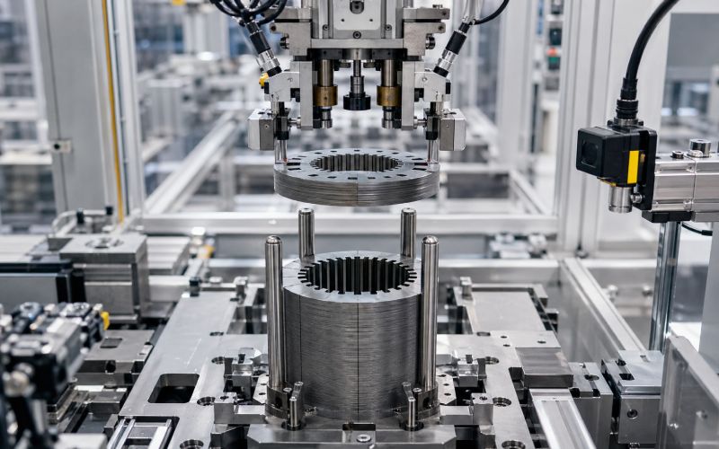
Motor lamination stacking is not just a sheet-handling process.
It is where a motor core quietly becomes good, unstable, expensive, or impossible to fix later.
This article explains how to design stacking automation for motor laminations using:
The focus is practical: how to catch problems before welding, bonding, winding, magnet insertion, shaft assembly, or final motor testing.
Because by the time a bad stack reaches the end of the line, it has collected labor, machine time, parts, and excuses.
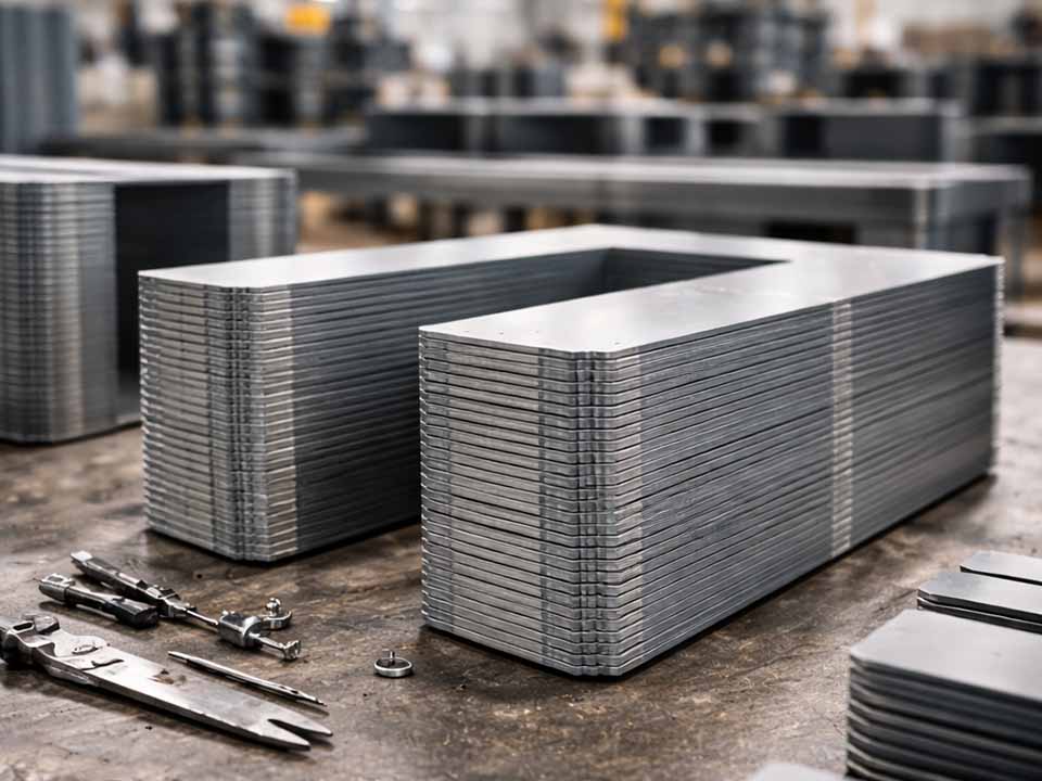
Motor lamination stacking is the process of assembling thin electrical steel laminations into a stator core, rotor core, segmented core, or sub-stack.
Each lamination is usually stamped or cut from electrical steel. The sheets are stacked together to form the magnetic core of the motor. The thin-sheet structure helps reduce eddy current losses, while the completed stack provides the geometry needed for winding, magnet placement, shaft fitting, housing assembly, and final motor performance.
That is the clean definition.
The production reality is messier.
Each lamination carries small variation:
One lamination may look acceptable. A few hundred of them can create a stack that is no longer acceptable.
That is why stacking automation matters.
It does not simply move sheets faster. It controls the way small errors accumulate.
A motor core is built in layers, but failures do not always appear layer by layer.
A stator stack can pass a basic height check and still create trouble during winding. A rotor stack can look clean before magnet insertion and still have pocket variation that causes assembly stops. A stack can reach its nominal height only because the press forced it there.
That last one is common.
The stack did not become good. It was compressed into silence.
Automation should prevent that kind of false confidence.
A well-designed lamination stacking cell helps reduce:
For high-volume motor production, the question is not only, “Can we stack this part?”
The better question is:
Can we prove every stack is correct before adding more cost to it?
Most lamination stack defects start small. That is what makes them irritating.
They are not always visible from across the line. They may not stop the machine immediately. They may wait until the next process, where they become someone else’s problem.
| Defect | What Usually Causes It | Where It Hurts Later |
|---|---|---|
| Double-sheet pickup | Poor separation, oil adhesion, magnetic attraction, vacuum error | Stack height, lamination count, joining quality |
| Missing sheet | Feed skip, failed pickup, sensor blind spot | Stack factor, height, magnetic performance |
| Angular misalignment | Pin clearance, worn datum, weak nest control, wrong placement path | Slot alignment, winding, magnet pocket position |
| Burr accumulation | Punch wear, burr direction inconsistency, poor deburring control | Slot insulation, stack seating, joining, assembly clearance |
| Local stack lift | Debris, burr, warped sheet, poor seating force | Flatness, welding/bonding quality, downstream fit |
| Wrong lamination variant | Similar parts, weak part verification, program mismatch | Scrap after joining or final assembly |
| Pin scraping | Tight clearance, burr, bent pin, poor chamfer | Coating damage, debris, stack drift |
| Coating damage | Rough handling, excessive compression, joining heat, pin friction | Interlaminar shorts, loss increase |
| Stack height drift | Thickness variation, compression change, missing/double sheet, tool wear | Assembly fit, magnetic consistency |
| Slot narrowing | Burr, angular drift, deformation, sheet mismatch | Winding insertion, insulation damage |
A stack can fail for one reason. It can also fail because three small reasons happen at once.
That is harder to catch. But not impossible.
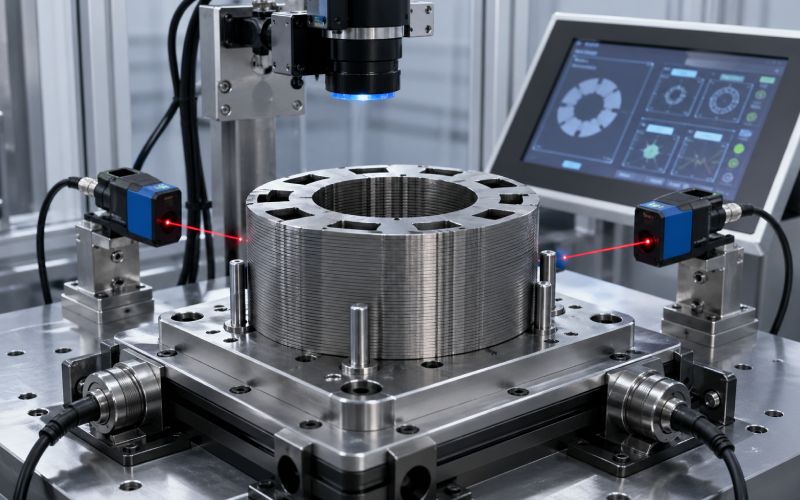
Sensors are not there to decorate the machine.
They answer specific questions at specific moments.
Before the sheet is picked:
Is the right part available?
During pickup:
Was one sheet picked, not two?
Before placement:
Is the lamination facing the right way and rotated correctly?
During stacking:
Did the sheet seat normally?
Before joining:
Is this stack worth welding, bonding, riveting, or pressing?
After joining:
Did the joining process create a good stack or just a permanent bad one?
That is the basic logic.
Do not add sensors because the machine has open space. Add sensors because the next operation makes a defect harder to recover.
The best sensor plan uses several simple checks instead of one “magic” inspection system.
A camera cannot feel seating force. A force sensor cannot identify a wrong lamination variant. A height sensor cannot prove the burr direction. A double-sheet sensor cannot confirm slot alignment.
So the system has to combine signals.
| Sensor or Check | Best Location | Main Purpose | What It Prevents |
|---|---|---|---|
| Part-present sensor | Feeder, pickup point, placement nest | Confirms lamination presence | Empty cycles, missing sheets |
| Double-sheet detector | Near pickup or transfer | Detects two laminations lifted as one | Wrong count, height error, scrap after joining |
| Vision inspection | Before stacking | Checks part identity, rotation, slot/key features | Wrong variant, angular error, upside-down sheet |
| Laser displacement sensor | During or after stack build | Measures stack height and local lift | Height drift, debris, poor seating |
| Multi-point height check | Pre-joining station | Detects tilt, waviness, uneven compression | Hidden flatness problems |
| Force-distance monitoring | Seating or compression step | Tracks how the stack behaves under load | Burr interference, misalignment, trapped debris |
| Pin load monitoring | Stacking fixture or mandrel | Detects side load, scraping, pin wear | Gradual alignment drift |
| Electrical short check | Post-joining or final stack gate | Checks unwanted conductive paths | Interlaminar short risk |
| Slot inspection | Pre-winding gate | Measures slot opening, burr risk, slot position | Winding damage, insertion stoppage |
| Bore or OD gauging | Rotor or stator final stack check | Confirms core geometry | Shaft fit, housing fit, balance risk |
The placement matters more than the catalog name of the sensor.
A sensor installed too far upstream confirms that something was correct earlier. That is not the same as confirming it is correct now.
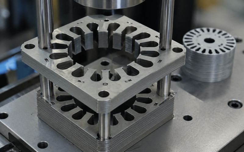
Stacking pins are locating elements used to align each lamination during stack build-up. They may locate through holes, slots, notches, inner diameter features, outer diameter features, or dedicated tooling features.
They sound simple.
They are not.
Pins control:
A worn pin may still allow production to continue. That is the danger.
The machine cycles. The stack looks normal. The dimensional trend moves slowly. Nobody notices until downstream failures begin.
Then people argue about winding, magnet insertion, welding, tooling, inspection, operators, and material.
Sometimes the pin was simply worn.
Pin design should not be copied from another cell without checking the part geometry and defect history.
| Pin Design Factor | Why It Matters | Poor Design Result |
|---|---|---|
| Lead-in chamfer | Helps thin laminations enter without catching | Scraping, bent edges, coating damage |
| Pin clearance | Balances location accuracy and smooth loading | Too tight causes jams; too loose causes drift |
| Pin hardness and coating | Controls wear and friction | Gradual loss of datum accuracy |
| Pin length | Supports stack height and sheet guidance | Leaning, poor stack control |
| Number of pins | Controls rotation and position | Too many can over-constrain the lamination |
| Pin replacement interval | Prevents silent drift | Batch-level misalignment |
| Cleanout path | Removes dust, chips, and coating debris | Local lift, jamming, false force spikes |
| Burr direction logic | Controls how burrs interact with pins | Poor seating, pin load increase |
More pins do not always mean better control.
Sometimes more pins mean the part has no freedom to settle. The stack fights the fixture. The force curve rises. The line keeps running anyway.
Not good.
A very tight pin fit can look attractive on a drawing. It promises control.
On the line, it may create the opposite.
Thin laminations are not perfect rigid plates. They have burrs, coating variation, oil, temperature effects, and handling variation. If pin clearance is too tight, normal variation becomes mechanical interference.
If clearance is too loose, the stack can rotate or drift.
So the correct pin clearance should be based on:
Do not set pin clearance from nominal CAD geometry alone.
That is a clean way to build a dirty problem.
Burrs are small on one sheet. In a stack, they become a pattern.
If burr direction changes randomly, the stack may show inconsistent seating, local height change, slot edge risk, or coating damage. If the burr always faces the same way, the stack may build more predictably, but burr accumulation still needs control.
For stator stacks, burrs near winding slots can damage insulation or interfere with wire, hairpin, or insertion tooling.
For rotor stacks, burrs near magnet pockets, bore features, or balancing-sensitive areas can create fit and performance issues.
A good stacking system should answer:
Burrs do not need to be dramatic to be expensive.
They only need to be repeated.
This is a common mistake.
Sheet count control verifies how many laminations entered the stack.
Stack height control verifies the physical height of the built stack.
They are related. They are not the same.
A stack can have the correct count and wrong height because of thickness variation, burrs, trapped debris, coating changes, or compression behavior.
A stack can have suspicious count behavior and still measure near target height because compression hides the error.
So a reliable stacking process should use both.
| Check | What It Answers | What It Cannot Prove Alone |
|---|---|---|
| Sheet count | Did the correct number of laminations enter the stack? | Whether all sheets seated correctly |
| Stack height | Did the stack reach expected build height? | Whether the count is correct |
| Multi-point height | Is the stack tilted, lifted, or uneven? | Whether the right lamination variant was used |
| Force-distance curve | Did the stack seat normally? | Exact dimensional compliance |
| Vision check | Is the part correct and oriented properly? | Whether the buried stack is seated correctly |
A single top-height measurement is better than nothing.
But it may miss tilt.
For motor cores with tight assembly requirements, use multi-point height checks before joining.
A force curve records force against distance or time during seating, compression, pin entry, or stack pressing.
It is useful because stack problems often show up as abnormal resistance before they show up as visible defects.
Force monitoring can detect:
Do not only watch peak force.
Peak force is easy to read, but it can hide the story.
A force-distance curve shows where resistance starts, how fast it rises, whether the stack settles smoothly, and whether the final seating behavior matches known-good stacks.
Two stacks may reach the same height.
One seated naturally.
One was forced there.
Those are different stacks.
A QC gate is a decision point where the system either releases the stack to the next step or stops it for rejection, rework, quarantine, or review.
QC gates should sit before cost increases.
That means before:
The worst place to discover a stacking issue is after the motor has already collected expensive downstream work.
| QC Gate | Process Location | What to Check | Why It Matters |
|---|---|---|---|
| Gate 1: Incoming lamination verification | Before feeding | Part type, lot, burr direction, visible damage | Prevents wrong material entering the cell |
| Gate 2: Pickup verification | At sheet pickup | Part present, single sheet, stable grip | Prevents missing or double sheets |
| Gate 3: Pre-stack orientation check | Before placement | Rotation, face direction, slot/key feature | Prevents buried orientation errors |
| Gate 4: In-stack monitoring | During build | Count, height trend, pin load, seating behavior | Catches drift before stack completion |
| Gate 5: Pre-joining gate | Before welding/bonding/riveting | Height, flatness, alignment, force signature | Avoids locking in bad geometry |
| Gate 6: Post-joining gate | After joining | Final height, bore/OD, slot position, short risk | Confirms joining did not damage the stack |
| Gate 7: Pre-downstream gate | Before winding, magnet insertion, shaft fit | Critical clearances and assembly features | Protects the next process from inherited defects |
End-of-line inspection still matters.
But it should not be the first serious inspection.
That is late learning.
A stacking automation project is not approved only because the fixture is clever.
It is approved because the line becomes more stable, scrap becomes earlier and cheaper, and failures become traceable.
| Engineering Problem | Automation Control | Business Impact |
|---|---|---|
| Double-sheet pickup | Double-sheet detection at pickup | Prevents joined scrap and rework |
| Slow pin wear | Pin load trend and scheduled replacement | Reduces batch-level drift |
| Burr growth | Force trend, vision, slot check | Protects winding and magnet insertion yield |
| Stack height variation | Count + multi-point height + compression data | Reduces assembly fit problems |
| Wrong lamination variant | Vision identity check and program lock | Prevents mixed-part production |
| Late defect discovery | QC gates before value-added steps | Lowers cost of poor quality |
| Unclear root cause | Stack ID traceability | Shortens troubleshooting time |
| Operator-dependent decisions | Defined pass/fail logic | Improves repeatability across shifts |
A good QC system does not only reject bad stacks.
It explains why they were rejected.
That explanation is where the money is.
The same defect has different cost depending on when it is caught.
A wrong lamination detected at pickup is a small event.
A wrong lamination detected after stack joining is scrap or rework.
A wrong lamination detected after winding, magnet insertion, shaft pressing, or final motor test is now a much larger problem.
| Defect Found At | Typical Cost Level | Why |
|---|---|---|
| Before pickup | Lowest | Sheet can be rejected before value is added |
| During stacking | Low | Stack can be stopped before joining |
| Before joining | Moderate | Some build time is lost, but major downstream cost is protected |
| After joining | Higher | Stack may require rework or scrap |
| After winding or magnet insertion | Very high | More components and machine time are already invested |
| At final test | Highest | Root cause is harder to isolate and containment is wider |
This is the business case for QC gates.
Not theory. Just arithmetic with better timing.
OEE is often discussed at the machine level, but lamination stacking defects spread across the whole line.
A stacking cell can damage OEE in three ways:
The line stops because of jams, double picks, pin interference, transfer faults, or unclear reject handling.
The line runs slower because the process needs repeated retries, manual checks, or unstable feeding.
The line produces stacks that later fail dimensional checks, joining checks, winding insertion, magnet insertion, or final test.
A better stacking system improves OEE by:
The aim is not maximum speed at all costs.
A fast stacking cell that sends defects downstream is not fast. It is borrowing time from the next station.
Motor lamination stacks may be held together by different joining methods. Each method changes the inspection risk.
| Joining Method | Main Benefit | Main QC Concern | Recommended Gate |
|---|---|---|---|
| Interlocking | Fast, integrated with lamination design | Local deformation, stress, stack separation, feature damage | Check interlock formation and stack flatness |
| Welding | Strong mechanical holding | Heat effects, local shorts, distortion, weld consistency | Pre-weld geometry + post-weld electrical/dimensional check |
| Bonding | Good surface contact and controlled stack behavior | Adhesive distribution, cure, pressure, contamination | Pressure/temperature/cure traceability |
| Riveting or mechanical fastening | Simple mechanical retention | Local deformation, clamp variation, hole alignment | Fastener force and post-assembly geometry |
| External clamping | Flexible for some assembly designs | Stack shift, compression loss, handling sensitivity | Compression and transfer verification |
There is no universal best method.
There is only the method that fits the motor design, volume, tolerance, magnetic performance target, and cost model.
But every method needs a QC plan that matches its failure modes.
This is a common comparison during process planning.
| Topic | Welding | Bonding |
|---|---|---|
| Cycle behavior | Often fast once positioned | May require cure time or controlled dwell |
| Mechanical retention | Strong local joining | Distributed surface retention |
| Heat input | Present | Usually lower heat, depending on process |
| Electrical short risk | Needs attention near joined areas | Depends on adhesive and surface condition |
| Distortion risk | Possible near weld zones | Depends on pressure, adhesive layer, and cure |
| Data to track | Weld energy, position, time, force, visual result | Adhesive amount, pressure, temperature, cure profile |
| Best QC focus | Pre-weld alignment and post-weld geometry/short checks | Surface cleanliness, pressure, cure, final height |
The decision should not be made from joining strength alone.
It should include downstream performance, inspection burden, equipment footprint, repair strategy, and traceability needs.
A joining method that is easy to install but hard to verify may become expensive later.
For stator lamination stacks, the process should protect the winding path.
Important checks include:
If the stator uses hairpin winding, slot geometry becomes even more sensitive. The insertion process does not forgive narrow slots, burrs, or angular drift.
A stator stack may look acceptable from the outside while one slot family is trending out of position.
So inspect the geometry that the next process actually uses.
Not just the geometry that is easy to measure.
For rotor lamination stacks, the highest-risk features are often different.
Important checks include:
Rotor stacks can create expensive downstream problems if the bore, magnet pockets, or skew features drift.
A small angular issue in the stack may become a magnet insertion issue. A bore error may become a shaft assembly issue. A stack imbalance issue may not be obvious until much later.
Again, late detection is the expensive version.
Segmented stator or rotor stacks add another layer of complexity.
Now the system must control not only sheet-to-sheet stacking, but also segment-to-segment relationships.
Check for:
Segmented designs can improve material use or assembly flexibility, but the stacking automation must manage accumulated error carefully.
One segment slightly off may pass.
Several segments slightly off may create a roundness or slot-position problem.
That is how accumulation works. Quietly.
Machine vision is useful when it is treated as a controlled measurement system, not a camera bolted near a conveyor.
Vision can inspect:
The difficult parts are lighting and repeatability.
Electrical steel can reflect light in ways that confuse edge detection. Oil film changes surface appearance. Burrs may only appear under certain light angles. Coating variation can change contrast.
A good vision setup needs:
Do not train or validate only on clean, perfect laminations.
Production parts are less polite.
Double-sheet pickup is one of the most important early checks.
Two thin laminations can behave like one sheet during pickup. Oil film, static, magnetic attraction, poor separation, or vacuum behavior can make this more likely.
A double-sheet event can cause:
Double-sheet detection should be placed as close to pickup or transfer as practical.
If it is too far upstream, it may confirm the wrong thing. A clean feed does not guarantee a clean pickup.
A stacking cell cannot inspect its way out of unstable feeding forever.
Good feeding should control:
If the feeder is unstable, the rest of the automation becomes reactive.
The line starts using sensors to catch problems that should have been prevented mechanically.
That may work for a while. It usually becomes maintenance-heavy.
Single-point height checks are common because they are simple.
They are also limited.
A stack can have correct height at one point and still be tilted. It can have local debris. It can have one side lifted by burr accumulation. It can be compressed unevenly.
Multi-point height measurement gives better information:
For tight stator or rotor assemblies, multi-point height is not overkill.
It is a way to avoid pretending a stack is flat because one sensor said so.
Modern lamination stacking automation should not only make a pass/fail decision.
It should produce usable production data.
Each stack should have a stack ID. That ID should connect the physical core to the data created during production.
Useful data includes:
This data can be sent to MES, SCADA, quality databases, or local traceability systems.
The goal is not to store everything forever.
The goal is to store enough to answer this question:
When a bad core appears later, what was already visible during stacking?
A lamination stacking cell may generate more data than a plant wants to store as raw files.
Force curves, camera images, height maps, and sensor logs can become heavy.
So the control architecture should separate:
A practical structure looks like this:
| Data Level | Example Data | Best Use |
|---|---|---|
| Real-time PLC data | Sensor state, actuator state, interlocks | Machine control |
| Edge processing data | Vision result, force curve features, height trend | Fast QC decisions |
| MES data | Stack ID, pass/fail, recipe, reject reason | Production tracking |
| Quality database | Trends, lot comparison, tool wear analysis | Root cause analysis |
| Archived raw data | Images, full force curves, detailed logs | Deep investigation when needed |
Not every image needs to go to MES.
Not every force curve needs to be stored forever.
But every rejected stack should have a reason code that people can understand.
“Fail” is not enough.
In a stacking cell, different sensors sometimes disagree.
A camera says the lamination is correct.
The force curve says seating was abnormal.
The height sensor says the stack is borderline.
The machine is asking a question.
Do not answer with automatic approval.
A strong reject logic should include:
Example:
| Signal Combination | Recommended Action |
|---|---|
| Vision pass + normal force + height pass | Release stack |
| Vision pass + force abnormal + height pass | Quarantine or secondary check |
| Vision fail + force normal | Reject or re-inspect before stacking |
| Count pass + height fail | Stop and investigate thickness, debris, seating |
| Count fail + height pass | Reject; compression may be hiding count error |
| Pin load rising over multiple stacks | Maintenance warning before hard failure |
| Repeated double-sheet events | Stop feeder and require recovery procedure |
Sensor disagreement is not an annoyance.
It is often the first useful sign.
It is tempting to write a universal tolerance.
Do not.
Motor lamination stack tolerances depend on:
A tolerance that is easy for one line may be impossible for another.
A tolerance that is acceptable for one motor may damage another motor’s yield.
Instead of copying numbers, define tolerance from four inputs:
This is slower than copying a number.
It is also less foolish.
Not every variation should stop the line.
A good process separates three levels.
| Limit Type | Meaning | Action |
|---|---|---|
| Control limit | The process is drifting but the part may still be usable | Alert, trend review, maintenance planning |
| Reject limit | The stack does not meet release criteria | Reject or quarantine the stack |
| Machine fault limit | The cell may keep producing defects | Stop the machine and require recovery |
This helps prevent two bad outcomes:
Operators learn quickly whether a QC system is useful or theatrical.
If the system creates too many weak alarms, people work around it.
So the alarm design matters.
Some process steps can be retried.
Some cannot.
Joining is often the point where bad geometry becomes permanent or expensive to undo.
That makes the pre-joining QC gate one of the most important gates in the cell.
Before joining, verify:
If the stack fails here, do not send it forward because production is behind.
That is how a small delay becomes a large containment problem.
A practical lamination stacking line may follow this structure:
Software sorting without physical sorting is not enough.
A bad stack sitting beside good stacks is still a risk.
Pin wear should be managed by condition, not only by time.
A good maintenance plan tracks:
A pin may not fail suddenly.
It may get worse slowly.
This is why trend data matters. It catches the boring failure mode.
And boring failure modes are the ones that make bad batches.
Automation does not remove judgment.
It moves judgment earlier.
Someone still has to decide:
The machine should not make unclear decisions quietly.
It should make defined decisions loudly enough that the right people can act.
Not emotionally. Just clearly.
Height is useful. It is not a full quality decision.
Use count, height, force, orientation, and key geometry together.
Pins are not permanent truth.
They wear, bend, scrape, collect debris, and lose accuracy.
If the first meaningful inspection happens after joining, the process has already lost control of cost.
Vision is strong for identity, orientation, and exposed geometry.
It cannot prove internal seating quality after the lamination is buried.
Overrides may be necessary.
Unrecorded overrides are not.
Large raw data archives look impressive.
Useful reason codes, trends, and stack-level traceability solve problems faster.
A tolerance without process context is just a number.
Use product need, downstream clearance, and process capability.
Digital rejection is not containment.
Bad stacks need controlled physical flow.
A mature stacking process is not dramatic.
It catches double sheets early.
It rejects wrong variants before stacking.
It sees pin wear as a trend.
It catches burr growth before winding failures begin.
It stops suspect stacks before joining.
It sends useful reason codes to the factory system.
It gives quality engineers enough data to solve problems without interviewing half the shift.
It does not rely on luck, memory, or someone standing near the machine at the right moment.
That is the point.
The stack should not have to fail loudly before the process listens.
Use this checklist when planning, specifying, or reviewing a stacking automation project.
| Question | Why It Matters |
|---|---|
| How does the system detect double-sheet pickup? | Prevents count and height errors |
| How does it verify lamination orientation? | Prevents buried wrong-layer defects |
| Are stacking pins monitored for wear or load? | Prevents slow alignment drift |
| Is stack height measured at one point or multiple points? | Detects tilt and local lift |
| Is force-distance data used during seating? | Finds hidden burr and seating problems |
| Is there a QC gate before joining? | Stops defects before they become expensive |
| Are reject reasons automatically recorded? | Supports root cause analysis |
| Can stack data connect to MES or traceability systems? | Links physical parts to process history |
| What happens when sensors disagree? | Prevents false-pass logic |
| Are rejected stacks physically separated? | Supports real containment |
| Is the system designed for real oily production parts? | Avoids validation surprises |
| Can the system handle part variants safely? | Reduces mixed-production risk |
A good supplier or internal engineering team should be able to answer these without long pauses.
Some pauses are fine.
Long pauses are data.
Use controlled sheet separation, stable pickup tooling, and a double-sheet detector near the pickup or transfer point. The check should happen before the lamination enters the stack. If a double sheet reaches joining, the cost of the defect increases quickly.
Common causes include lamination thickness variation, burr growth, missing sheets, double sheets, debris between layers, coating variation, uneven compression, and poor seating. Stack height should be checked together with sheet count and force behavior.
For basic stacks, one point may be enough for rough confirmation. For tighter motor cores, multi-point height measurement is better because it can detect tilt, local lift, waviness, and uneven compression before joining.
Worn pins lose datum accuracy. The stack may still load and cycle normally, but angular position or radial location can drift over time. Pin wear should be tracked using inspection, pin load trends, force signatures, and reject data.
Common sensors include part-present sensors, double-sheet detectors, vision systems, laser displacement sensors, force sensors, pin load monitors, electrical short checks, and dimensional gauging. The right mix depends on the motor core design and downstream assembly risk.
Burrs can increase resistance during placement, seating, or compression. A force-distance curve can show abnormal contact, scraping, sudden resistance, or excessive compression before the defect is obvious visually.
Sheet count verification confirms how many laminations entered the stack. Stack height control confirms the physical height of the stack. Both are needed because compression, thickness variation, or double-sheet events can make one check misleading by itself.
Use vision inspection, dimensional gauging, or slot-specific measurement before the winding process. Focus on slot opening, slot depth, burrs, tooth alignment, and angular position. The inspection should match the winding method and insertion clearance.
Because software rejection alone does not prevent mix-ups. Rejected and quarantine stacks should move to controlled locations so they cannot accidentally enter joining, winding, magnet insertion, or final assembly.
It improves OEE by reducing unplanned stops, preventing downstream failures, lowering rework, improving first-pass yield, and giving maintenance teams clearer defect signals. The strongest OEE gains often come from stopping defects before they leave the stacking cell.
Motor lamination stacking automation is not only about speed.
Speed matters, yes. But speed without early defect control just moves bad stacks faster.
The stronger goal is this:
Build each stack with controlled alignment, verified count, measured height, known seating behavior, clear QC gates, and traceable data before the next process adds cost.
That is how stacking automation protects yield, OEE, and downstream assembly.
And it starts with simple questions asked at the right time:
Was the right sheet picked? Was it only one sheet? Was it placed correctly? Did it seat normally? Is the stack still healthy before joining? Can the data prove it?