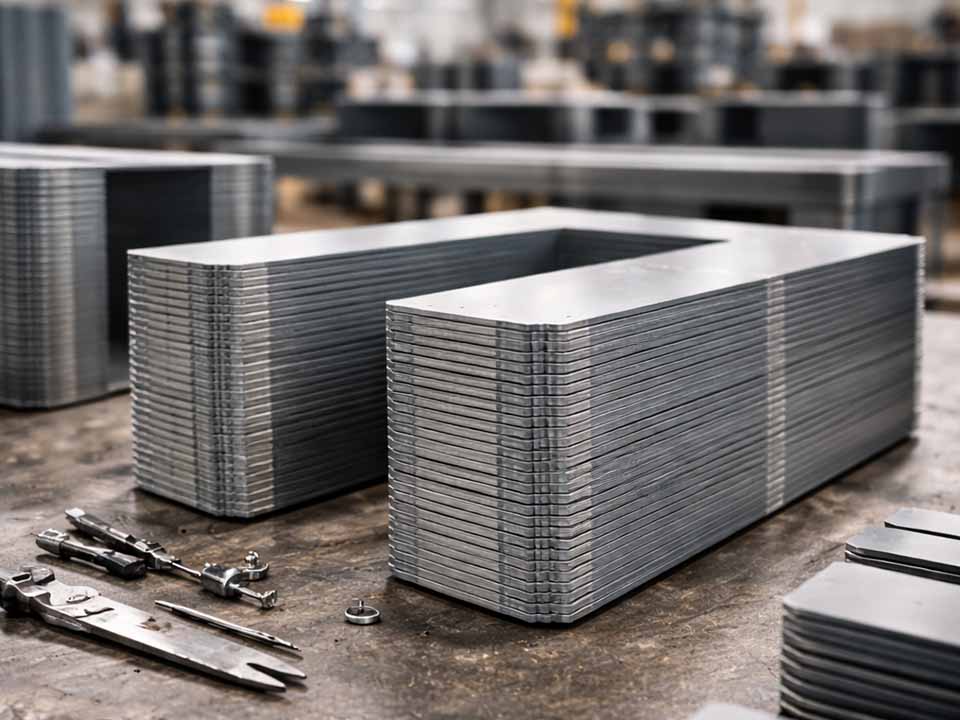
Let Sino's Lamination Stacks Empower Your Project!
To speed up your project, you can label Lamination Stacks with details such as tolerance, material, surface finish, whether or not oxidized insulation is required, quantity, and more.
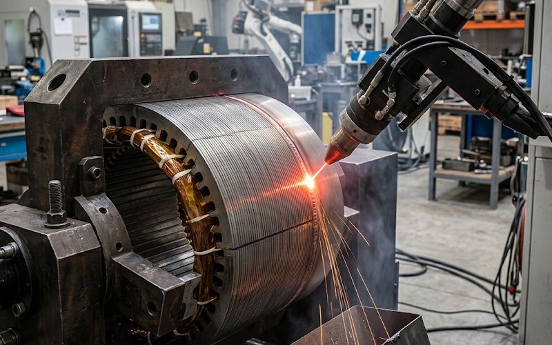
If distortion is the problem, start here: cut heat input, clamp the stack more evenly, and stop running more weld than the joint actually needs. For most motor lamination stacks, laser welding gives a wider process margin than TIG when dimensional stability and magnetic performance matter at the same time, because the heated zone is smaller and the damage is easier to localize. TIG can still make sense when joint strength is the main constraint, but it usually asks for a larger thermal price. That price shows up as pull, residual stress, coating damage, and sometimes a quiet rise in core loss that is not obvious until later.
That is the real trap with lamination stack welding. A weld that looks mechanically solid can still be the step that hurts the motor. Thin electrical steel laminations are there to limit eddy currents. Welding, especially when the seam is too long or too hot, can connect layers electrically, damage the insulation coating, and introduce local stress that worsens magnetic behavior. Multiple studies on welded electrical steel stacks report higher iron loss after welding, and the effect tends to grow as the welded region grows.
So the goal is not “maximum penetration” or “the strongest bead possible.” Not really. The goal is a joint that is just strong enough, in the least harmful location, with the smallest thermal footprint the application can tolerate. That is how distortion gets controlled before it becomes a rework problem.
Before getting into process details, these are the levers that matter most in practice:
That list sounds plain. It should. Distortion in lamination stacks is usually not caused by one dramatic mistake. It is the accumulation of smaller ones. A little too much weld length. A little uneven clamp pressure. A seam placed where the housing fit has no forgiveness. Then the stack pulls.
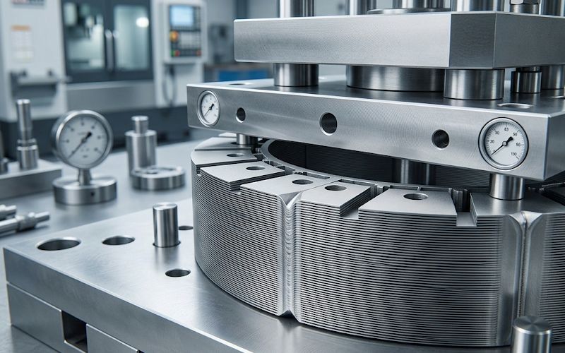
A lamination stack is not a solid ring or a solid bar. It behaves like a layered structure with tiny interfaces, small gaps, coating thickness variation, burrs, and local stiffness changes from sheet to sheet. Heat one edge and the stack does not respond as one clean block. Some laminations move. Some bridge. Some stay pinned by the fixture while adjacent layers shrink differently during cooling. The result is usually local pull, OD seam height growth, bow, runout, or twist. Residual stress is part of that story too, and in electrical steel it matters twice: once for shape, once for magnetic performance.
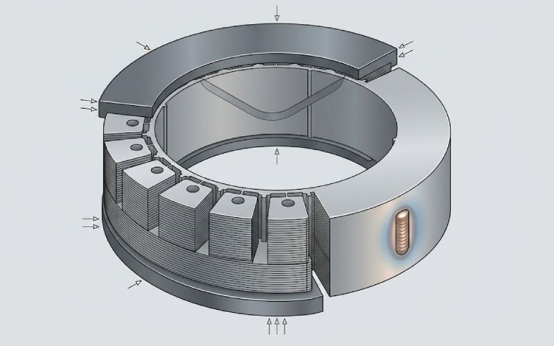
There is another issue. Welding is not just joining the laminations mechanically. It also changes the electrical and metallurgical condition near the seam. Coatings can degrade. Interlaminar resistance can drop. The seam can act like an electrically connected edge. Recent review work on stator core joining points out that welded seams are often placed on the outer diameter and may even need a recess because seam geometry can interfere with later press-fit or shrink-fit assembly into a housing. That is not a cosmetic nuisance. It is a production problem.
Laser welding is usually the safer default for lamination stacks when the main risks are distortion, coating damage, and magnetic-property loss. The reason is straightforward: the energy is more concentrated, the heat-affected zone is smaller, and the seam can be kept narrow. Comparative work on laminated electrical steel has found that laser welding generally preserves magnetic properties better than TIG, even when TIG produces stronger joints. Pulsed laser approaches can also reduce the increase in iron loss compared with more thermally aggressive continuous laser conditions, provided the parameters stay within a stable window.
That does not mean laser is automatically safe. A laser seam that is too deep, too long, too continuous, or too close to a critical fit surface can still pull the stack and still create an oversized damaged zone. The process margin is wider, yes. It is not infinite.
TIG welding can be useful when joint strength requirements are high, production volume is lower, or the process route is already established and well controlled. But for lamination stacks, TIG usually makes distortion control harder because the thermal input is broader and the molten zone is less localized. Studies comparing laser and TIG on non-oriented electrical steels have shown a larger drop in magnetic performance with TIG, even where the welded joint strength was higher. That trade-off matters. A strong joint is not enough if the stack becomes harder to assemble or less efficient in service.
So the process choice is often simple:
This is where many technical articles get vague. They talk about “optimizing parameters” and leave it there. That is not enough. A useful process window for lamination stack welding should connect four things: part condition, welding variables, geometry targets, and release checks.
Before any weld settings are chosen, lock down these inputs:
Without these, a so-called parameter window is guesswork. The same weld layout that is harmless on a shorter, thicker stack can be too aggressive on a tall stack with thinner laminations.
For distortion, the priority variables are not mysterious:
Research on laser spot and seam welding of electrical steel supports the same direction: smaller heated zones and more controlled energy input tend to reduce both mechanical distortion and magnetic damage, while excessive bead area or aggressive continuous welding tends to increase iron loss and stress effects.
A distortion-control process window is incomplete unless it includes acceptance targets after welding. In practice, that means defining limits for:
This matters because two parts can have similar-looking welds and very different assembly behavior. One slips into the housing. One catches on the seam and forces a secondary operation.
If the motor design is sensitive to stator losses, then post-weld release should not depend on geometry alone. Add checks such as:
Welding studies on electrical steel consistently show that joint area, thermal severity, and residual stress can change iron loss measurably. That is why a visually acceptable seam is not enough.
| Symptom after welding | Most likely driver | What it usually means | First correction to try |
|---|---|---|---|
| Stack bows or pulls to one side | Heat input too high or sequence is unbalanced | Shrinkage is accumulating in one direction | Shorten seam length, split the weld pattern, rebalance sequence |
| OD seam sits proud and interferes with assembly | Seam volume too large or seam placed on a critical fit surface | Bead geometry is exceeding fit tolerance | Reduce weld volume, recess the weld, move the weld away from the fit surface |
| Local layer lift or inconsistent seam depth | Clamp pressure is uneven | Laminations are moving during welding | Improve fixture contact and equalize compression through stack height |
| Good joint strength but worse core performance | Welded zone is too large or too electrically connected | Magnetic damage is outrunning mechanical benefit | Reduce bead area, reduce penetration, replace continuous welds with shorter distributed joints |
| Pores, erratic fusion, or spatter | Poor edge condition or coating contamination in the weld zone | The incoming stack is unstable before welding begins | Clean edges, reduce burrs, stabilize stack preparation |
| Part looks straight free-state but shifts during housing fit | Weld location and seam geometry are incompatible with downstream assembly | The seam is creating an assembly interference or local stress concentration | Review weld placement, proud height, and fit-up sequence |
This table is not a substitute for testing. It is a decision shortcut. Distortion control usually improves faster when the first response is about heat, layout, and restraint, not cosmetic tweaking.
General distortion-control guidance in welding has been consistent for years: use the minimum weld volume that still meets the joint requirement, and avoid long runs when shorter runs will do. For lamination stacks, the case is even stronger because a long seam creates a long shrinkage path and a larger damaged magnetic zone at the same time.
If the design allows several short welds instead of one continuous weld, that is often the better direction. Distributed spot or short-seam strategies can reduce shrinkage concentration and limit the electrically connected path along the stack edge. In electrical steel joining studies, this kind of pattern has been explored specifically to reduce the penalty that comes with larger welded areas.
Outer-diameter welds are common because they leave the active tooth region less disturbed and are easier to access. But common is not the same as harmless. If the stack is going into a tight housing, a proud seam on the OD can create direct fit problems. Recent review work notes that recessed weld placement is often used for exactly this reason.
A stack that is not uniformly compressed before welding is already halfway to distortion. That sounds obvious. It still gets missed.
The fixture has to do three things at once:
Experimental work on laser spot welding of electrical steel laminations shows that modest but stable contact pressure can be enough to keep lamellae fixed during joining. The lesson is not a universal pressure number. The lesson is that uniformity matters. A fixture that clamps hard in one zone and barely touches another invites inconsistent seam formation and layer movement.
Do not treat welding as the stage that fixes poor stack preparation. It rarely does.
If burrs are excessive, if coating is damaged, if edges are dirty, or if lamination flatness is unstable, the weld pool becomes less predictable and the chance of unwanted interlaminar bridging goes up. Coating degradation products can contribute to porosity and other seam defects as well. By the time this shows up on the weld, the root cause is usually upstream.
A cleaner rule is this: a stable weld begins with a stable stack. That means controlling incoming lamination quality, stack alignment, burr direction, and pre-weld compression before the arc or beam ever starts.
A lamination stack weld should not be released just because it “looks clean.” That is too weak a standard.
A stronger inspection routine checks four layers of evidence:
Measure flatness, runout, stack squareness, OD seam proud height, and any local pull near the weld.
Review sections of approved samples to confirm actual penetration depth, affected zone size, and whether fusion is larger than intended.
Where performance is sensitive, verify interlaminar insulation condition and compare core loss against a reference condition or control sample.
Run defined destructive tests or retention checks at a practical sampling frequency, based on the real job of the weld.
This is the point many teams skip. Then they spend time solving “assembly variation” or “unexpected efficiency drop” as if those are separate issues. Sometimes they are not separate at all. They started at the weld.
That logic works for many fabricated parts. It works less well here.
Settings alone do not protect the part.
They often do look robust. They also concentrate shrinkage and enlarge the damaged zone.
A seam that survives welding but collides during insertion is not a good seam.
They are not. The thermal behavior is different, and the distortion risk is different.
Not always. But when the main risk is distortion, residual stress, or magnetic-property loss, laser is usually the better starting point because it can localize energy more effectively and reduce the affected zone. Comparative studies on electrical steel laminations found that TIG can produce stronger joints while causing greater magnetic degradation.
Yes. In lamination stacks, larger or more severe welds can increase the damaged zone, reduce insulation integrity between laminations, and raise iron loss. More weld is not automatically better. It can improve retention while hurting efficiency.
If the design allows it, several short welds or distributed weld points are often better for distortion control than one long continuous seam. The reason is simple: less concentrated shrinkage, less total damaged edge, and better control of how the stack moves during cooling.
Yes. Uneven clamping allows local sheet movement during welding, and that can produce inconsistent penetration, seam irregularity, and post-weld pull. Stable, uniform compression is one of the cheapest and most effective ways to reduce distortion before it starts.
It can improve dimensions. It does not restore damaged insulation or remove residual stress effects that may already be influencing magnetic performance. So straightening can be useful, but it is not a full repair for welding damage in electrical steel stacks.
At minimum: geometry, seam height, runout, fusion size, retention strength, and where relevant, electrical insulation condition or core loss behavior versus a reference. A good-looking bead is not enough.
To avoid distortion in motor lamination stack welding, do not begin with the weld bead. Begin with the stack, the fixture, and the heat budget.
Use laser by default when you need a smaller thermal footprint. Use TIG carefully when its joint characteristics are truly needed and the part can absorb the larger thermal effect. Keep seams shorter. Spread them when possible. Clamp the stack evenly. Protect critical fit surfaces. Then verify the result with geometry and performance checks, not appearance alone.
That is the practical rule behind most successful lamination stack welds. They are not the biggest welds. They are the most controlled ones.