Let Sino's Lamination Stacks Empower Your Project!
To speed up your project, you can label Lamination Stacks with details such as tolerance, material, surface finish, whether or not oxidized insulation is required, quantity, and more.
TL;DR
- Choose riveting when stack integrity during handling, winding, press-fit, or vibration is the bigger risk, and when you can keep holes in lower-flux regions.
- Choose clinching when high-volume stamping and integrated stacking matter more, but only if interlock count, depth, clearance, and pair layout are controlled like magnetic design variables, not just tooling details.
- The magnetic penalty is not vague. In one stacked-core study, a hole-only condition raised iron loss by about 6.2% at 1.0 T, 50 Hz, dowel formation raised it to about 9.1%, and the joined dowel condition reached about 13.1%. In denser interlock layouts from the same study, the increase reached 40.9%. By contrast, one pin-hole study found that a 6 mm hole could keep added loss under 1% when size and position were chosen carefully.
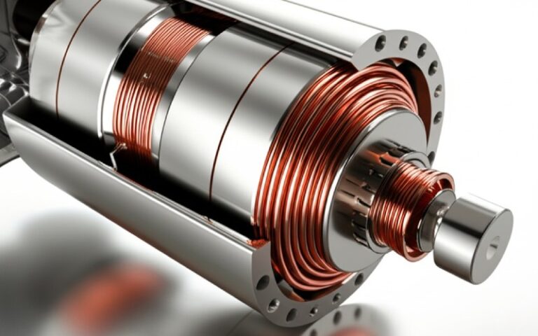
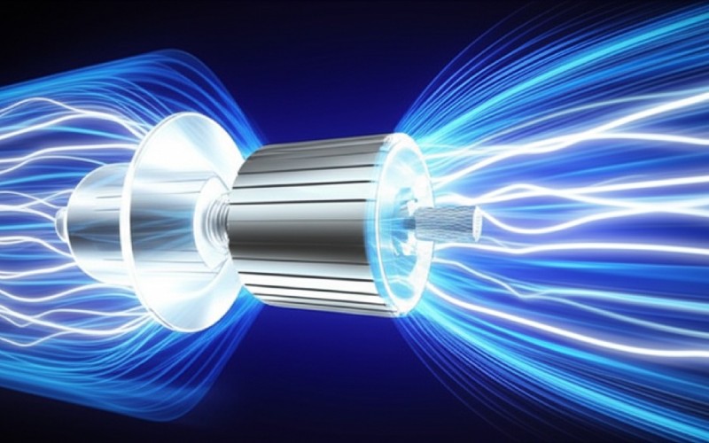
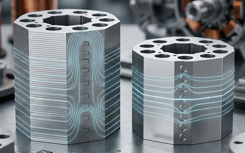
Lamination stacks only work because each sheet is insulated from the next. That sounds obvious. It matters anyway. The moment a joining method adds local strain, breaks coating, or creates a conductive bridge, the stack stops behaving like the clean stack in the electromagnetic model. Review work on electrical-steel manufacturing keeps landing in the same place: joining affects permeability, hysteresis loss, eddy-current loss, and local heat generation, sometimes all at once.
So the real question is not which method is stronger. It is narrower than that. More useful too. Which method is strong enough for the mechanical job, with the smallest magnetic penalty you can actually hold in production?
If the stack is likely to be punished mechanically — transport, winding tension, housing insertion, press-fit load, vibration, speed-related stress — riveting is usually the safer direction. If the stack is being built in volume and the factory wants the laminations to self-stack inside the progressive die, clinching has a clear process advantage. But once speed rises, flux rises, or joint density spreads into the active path, clinching starts charging interest.
That is the whole trade in one line: riveting tends to buy mechanical margin; clinching tends to buy manufacturing efficiency. Neither one is magnetically free.
Three mechanisms do most of the damage.
That split matters because riveting and clinching do not pay the same tax.
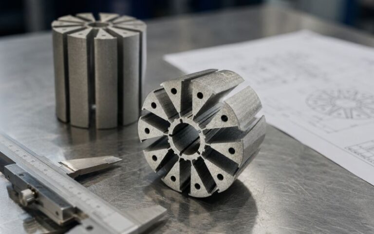
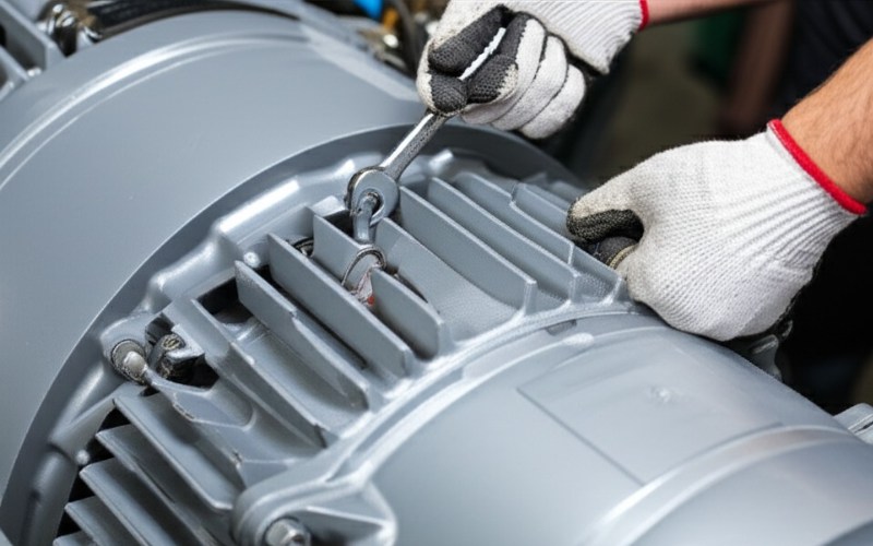
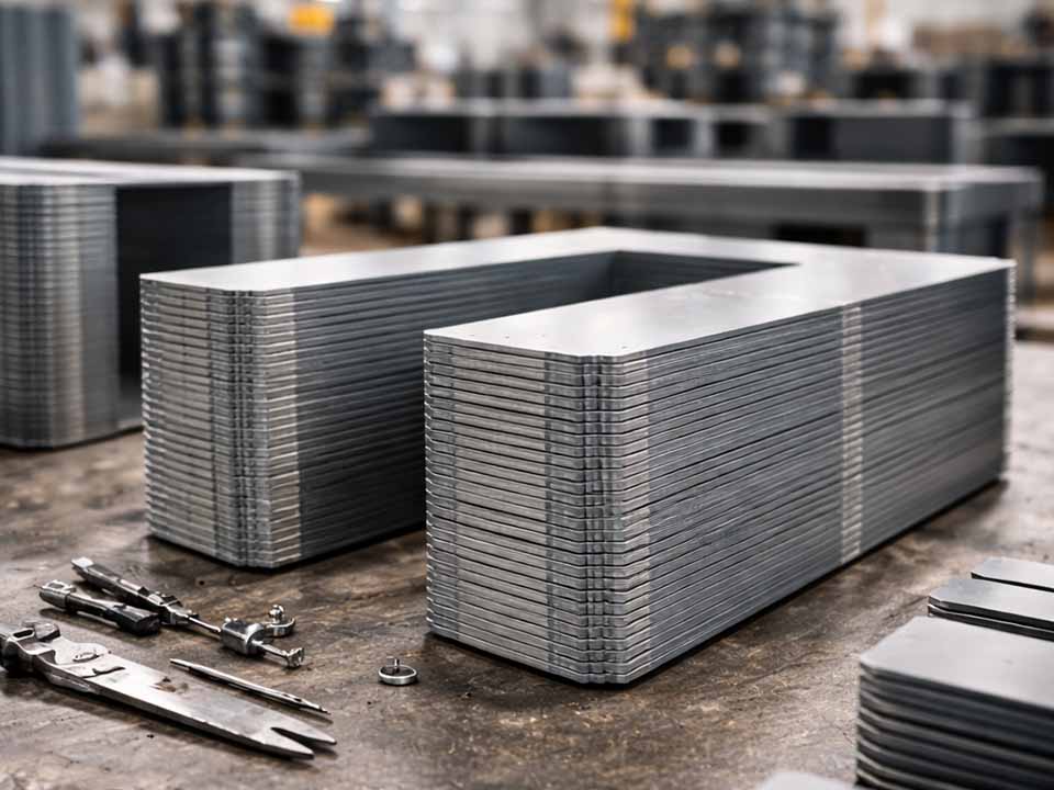
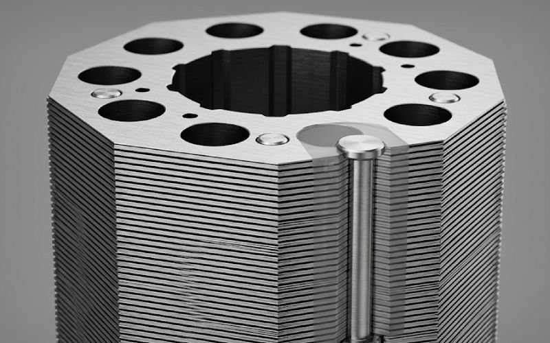
In this article, riveting means the stack is secured by a discrete fastener through a hole pattern. Mechanically, that is easy to understand and easy to audit. Hole size is visible. Clamp load is visible. Joint count is visible. For larger stacks or rougher assembly conditions, that kind of explicit retention still has a lot going for it.
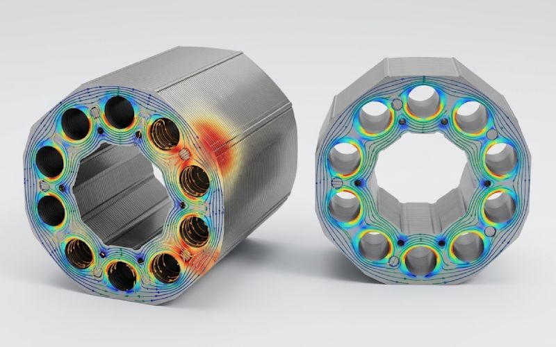
The magnetic side is where engineers get tripped up. The hole itself is already a disturbance. A transformer-core pin-hole study found that increasing hole diameter visibly raised core loss, with a 6 mm hole producing an increase of under 1%, while moving to 10 mm pushed the change to about 6.39% in that case. The same study also found that placing holes where flux distribution is lower reduced the penalty. A separate review on axial clamping of laminated cores makes the same placement point: holes for through-bolt clamping belong in lower-flux regions.
There is a second layer. In a stacked-core study that separated hole-making from dowel formation and jointing, the hole-only condition increased iron loss by about 6.2% at 1.0 T, 50 Hz. At 1.5 T, 50 Hz, the same hole effect was still there but narrower, about 6.3%. So riveting is not “magnetically neutral” just because it avoids interlock nubs. Holes still cost something. Usually less than a bad clinch pattern. Not always less than a good one.
The practical reading is plain enough: small holes, low-flux placement, limited count. That is where riveting starts to look sensible.
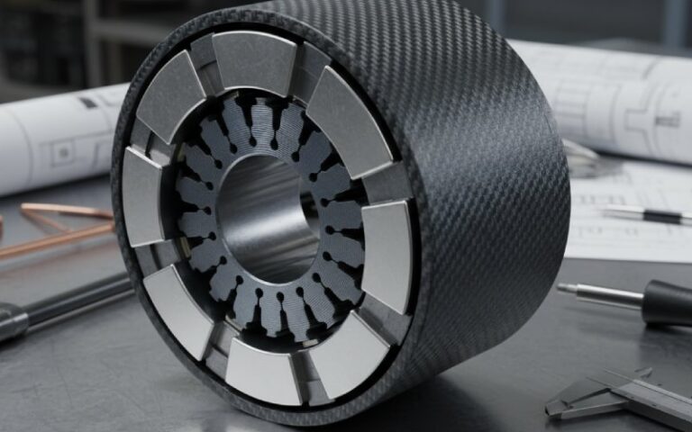
Clinching, or interlocking, is attractive because it can be built into the stamping route. Recent production work on punching dies describes interlocked cores being positioned and combined directly at the final station, while non-interlocked routes often still need off-line collecting, counting, shaping, and later joining. Separate cost work on lamination tooling reaches a similar conclusion from the die side: tooling cost tracks lamination size, part complexity, production scenario, and especially the number of progressive-die stations.
That is why clinching keeps showing up in volume programs. Fewer touch points. Less downstream handling. No separate fastener hardware. The process is neat.
Then the magnetic bill arrives.
A review of joining methods reports that interlocking is highly efficient as a process, but it is not strong and can only absorb low mechanical forces. The same review summarizes measured evidence that the inverse of permeability and iron loss both increase linearly with the number of interlocks, and that radial interlocks are more harmful than circumferential ones. Dowel width matters too: narrower dowels tend to reduce loss.
The more useful numbers come from stacked-core measurements. In one study, at 1.0 T, 50 Hz, a single joined-dowel configuration increased iron loss by about 13.1% relative to the no-dowel reference. When the interlock layout became denser, the increase climbed to about 20.6%, 23.5%, 31.9%, and finally 40.9% depending on configuration. At 1.5 T, 50 Hz, the same sequence was milder but still meaningful: about 7.6% up to 28.3%. Same joining family. Very different outcome, depending on pattern.
That is the point many selection guides miss. Clinching is not one process result. It is a whole family of outcomes.
Because there are two penalties, not one.
The first penalty is local material damage. Dowel formation plastically deforms the steel. In the same stacked-core work, the dowel-formed but not yet joined condition raised iron loss by about 9.1% at 1.0 T, 50 Hz. Then joining the dowel pairs pushed the increase to 13.1%. That split is important: part of the damage comes from making the feature, then more comes from forcing the joint.
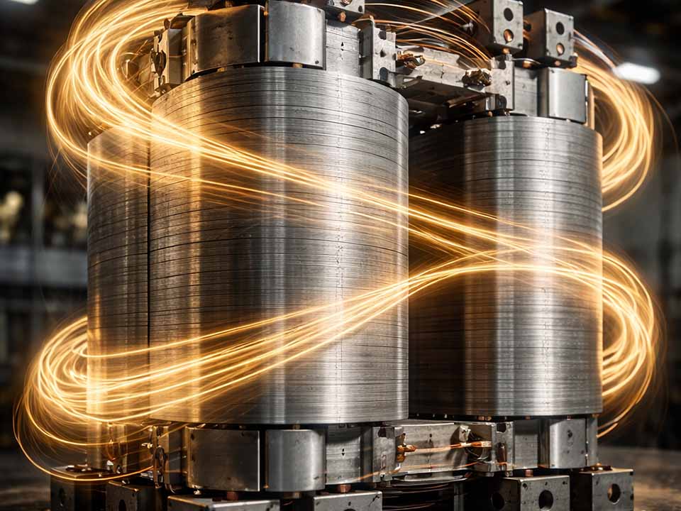
The second penalty is electrical. Once certain interlock pairs sit in a layout that lets flux link a conductive loop, extra eddy-current loss appears. The same study found that this extra loss increases linearly with the density of interlocking pairs, and that the problem becomes much more obvious at 400 Hz than at 50 Hz for the affected layouts. In other words, dense or badly placed interlocks are not just a low-frequency nuisance. They age badly as frequency rises.
If your machine is high-speed, this matters more. Not less.
The table below mixes data from different studies and geometries, so it is not a one-to-one design limit. It is still useful. It shows where the penalty starts, and how steeply it can grow.
| Decision factor | Riveting | Clinching / interlocking | What the numbers suggest |
|---|---|---|---|
| Primary mechanical logic | Discrete fastener through a hole pattern; retention is explicit | Formed nubs lock sheets together during or right after stamping | Riveting is usually chosen when retention margin matters more than die integration |
| Baseline magnetic penalty | Hole-only condition in one stacked-core study: +6.2% iron loss at 1.0 T, 50 Hz; in one pin-hole study, a 6 mm hole stayed under 1% added loss when optimized | Dowel formation alone: about +9.1%; joined dowel: about +13.1% at 1.0 T, 50 Hz | A well-managed hole pattern can be cheaper magnetically than a poor clinch pattern |
| Penalty at higher joint density | Mostly driven by hole size, count, and placement | Dense layouts reached about +40.9% at 1.0 T, 50 Hz and +28.3% at 1.5 T, 50 Hz in one ring-core study | Interlock count and layout can dominate the answer |
| Frequency sensitivity | Eddy-current penalty grows if holes or damaged insulation disturb the path | At 400 Hz, some interlock layouts showed markedly stronger extra loss because conductive loops formed between interlock pairs | High-speed machines are less forgiving of clinch geometry |
| Process window | More tolerant mechanically once the hole pattern is fixed | For 0.5 mm sheets in one study, no permanent joint formed below roughly 70–75% embossing depth; poor stacking occurred when clearance exceeded 4% of sheet thickness | Clinching works best when process control is tight and stable |
| Cost and throughput logic | Separate joining route; more downstream handling is common | Can be integrated into the progressive die; that reduces off-line stacking and joining work | Buyers should compare higher die complexity against lower assembly touch labor |
There is no universal dollar figure here because tooling cost depends heavily on part size, geometry complexity, and the number of stations in the progressive die. Published cost modeling for lamination stamping is explicit on that point. Production scenario changes the die, and the die changes cost.
Still, the commercial split is pretty stable.
Clinching usually makes sense when the line wants to self-stack parts in the die and protect throughput. Riveting usually makes more sense when the buyer is willing to accept a separate joining route in exchange for stronger retention and a more conservative mechanical joint strategy. So the real purchasing question is not “which is cheaper?” It is this:
Where do you want the cost to sit — inside the die and process-control burden, or downstream in hardware, handling, and assembly?
That one tends to end meetings faster.
A few rules show up across the literature often enough to be treated seriously.
This is explicit for hole-based clamping, and the same logic usually helps with clinch placement as well. If a joint sits in a quieter magnetic area, the penalty is easier to live with.
Interlock-related loss rose with the number of dowels and with the density of interlocking pairs. More points may improve retention. They can also turn a manageable loss increase into a bad one.
For interlocking, embossing depth, clearance, and tool-edge condition all move the result. In one 0.5 mm study, proper embossing depth varied from 0.36 mm to 0.39 mm depending on the sheet, and stacking quality degraded when clearance exceeded 4% of sheet thickness. That is not a small sensitivity.
Review work reports that post-joining annealing lowers core loss and improves magnetic performance. It will not remove every geometry penalty. It can reduce the stress-driven part of the penalty enough to matter.
If you are writing an RFQ, a process FMEA, or a design review checklist, ask for these items:
That last point is where a lot of bad choices survive longer than they should.
Not always, but it is usually the more conservative choice when the stack must survive handling, winding, insertion, or vibration without relying on a narrow forming window. Review work on joining methods describes interlocking as efficient but limited to low mechanical-force absorption.
No. A sparse, well-placed interlock pattern can outperform a poor hole layout. But once interlock density rises, or the pair geometry creates conductive loops, the loss penalty can grow much faster than many engineers expect. In one study, dense interlock layouts reached +40.9% iron loss at 1.0 T, 50 Hz.
Neither is clean. Hole-only fastening in one stacked-core study added about 6.2% iron loss at 1.0 T, 50 Hz. Dowel formation alone added about 9.1%, and a joined dowel about 13.1%. That does not make riveting universally better. It does show why small, low-flux holes are often easier to control magnetically than dense interlocks in active regions.
Very. For 0.5 mm sheets in one study, no permanent joint formed below roughly 70–75% embossing depth, and stacking quality became poor when clearance exceeded 4% of sheet thickness. Tool wear changed the usable depth window as well.
As far from the high-flux path as the mechanical design allows. Both clamping guidance and pin-hole loss studies point the same way: lower-flux placement reduces the loss penalty.
It can recover part of the stress-related damage, yes. It cannot fully erase a poor geometry or a conductive short-circuit path that the joint itself created. Think of annealing as damage reduction, not absolution.
If your program is limited by mechanical risk, riveting is usually the safer answer.
If your program is limited by throughput and integrated manufacturing, clinching is often the better answer.
If your program is limited by efficiency at higher frequency, be careful with clinching density and pair layout before you trust the process just because it looks elegant on the die drawing.
That is the real trade. Not strength versus loss in the abstract. Retention margin versus magnetic damage, under actual production conditions.