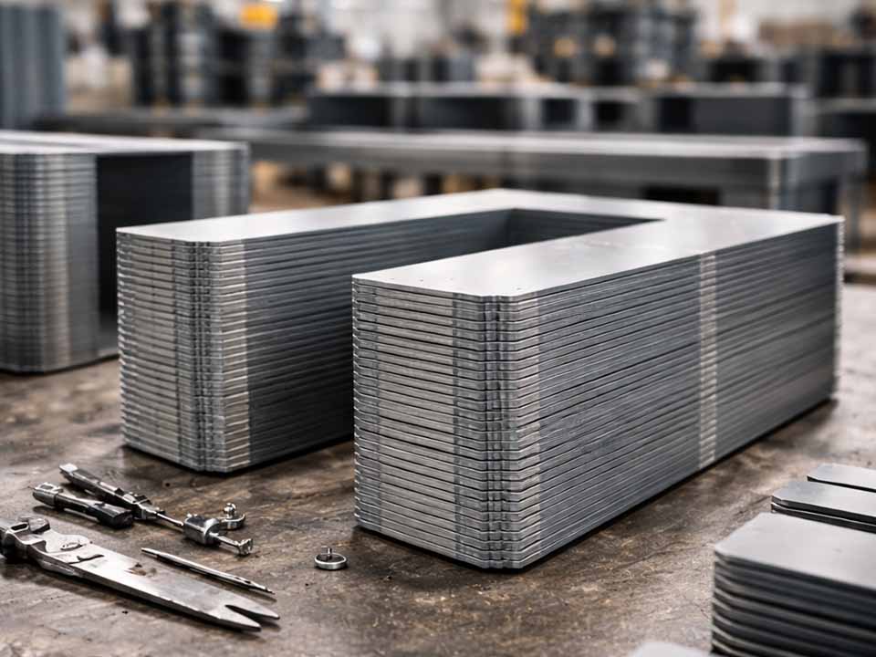
Let Sino's Lamination Stacks Empower Your Project!
To speed up your project, you can label Lamination Stacks with details such as tolerance, material, surface finish, whether or not oxidized insulation is required, quantity, and more.
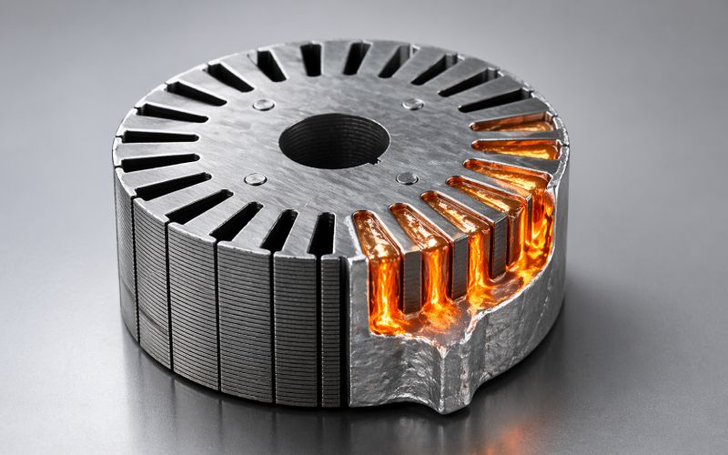
In an aluminum die cast rotor, the lamination stack is not just a stack of electrical steel.
It becomes part of the mold cavity.
That small shift in thinking changes almost everything. The molten aluminum does not see “motor design intent.” It sees narrow slot openings, sharp transitions, steel walls, burrs, coatings, skewed passages, and places where air has no easy escape.
A rotor can look correct in the drawing and still be difficult to cast.
This is why many aluminum rotor casting defects begin before the casting machine runs. They begin in the lamination geometry.
The slot may be too restrictive. The end-ring transition may be too abrupt. The skew may be useful electrically but awkward for flow. The bridge may satisfy magnetic requirements but freeze the aluminum too early near the slot opening.
None of these issues is dramatic on its own. In production, they stack up. Literally.
During aluminum rotor die casting, molten aluminum fills the rotor slots inside the lamination stack and forms the end rings at both ends. The result is a conductive squirrel cage.
The cast aluminum normally includes:
The rotor bars and end rings must form one continuous electrical cage. If one bar is porous, thin, cracked, or poorly connected to the ring, the rotor may still rotate. That does not mean it is healthy.
A defect inside the cage can change local resistance. It can disturb current distribution. It can increase heat. It can create torque ripple or vibration.
Sometimes the motor fails testing. Sometimes it passes testing and runs hot later. That is worse.
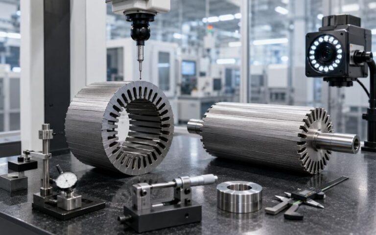
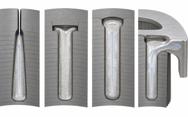
A lamination stack is built from many thin sheets. Each sheet has punched or stamped slot geometry. When stacked together, those openings form long internal passages for aluminum.
But the internal cavity is not as clean as the CAD model.
Real stacks include:
The aluminum responds to the real cavity, not the nominal cavity.
That is why rotor die casting cannot be separated from lamination stack design. The stack controls where the aluminum flows, where it slows down, where it traps gas, and where it freezes first.
A good rotor lamination design is not only efficient magnetically. It is castable.
| Lamination geometry factor | Casting effect | Common defect risk | Better design direction |
|---|---|---|---|
| Slot opening width | Controls entry of molten aluminum into the rotor bar cavity | Short shot, cold shut, incomplete fill | Avoid overly narrow slot mouths unless casting trials support them |
| Slot bridge thickness | Changes heat extraction and local restriction near the slot top | Early freezing, poor slot-top fill, weak bar section | Balance magnetic needs with casting flow and thermal behavior |
| Slot depth | Increases bar length and flow distance | Mid-slot porosity, incomplete fill, gas entrapment | Check fill stability across the full stack length |
| Bar cross-section | Determines conductive area and aluminum volume | High resistance, uneven current, low fill factor | Design for repeatable cast area, not only theoretical area |
| Slot taper | Influences flow speed and feeding direction | Isolated shrinkage, trapped air pockets | Use smooth transitions; avoid sudden pockets |
| Rotor skew | Extends flow path and changes slot alignment | Filling imbalance, torque loss if excessive, hidden porosity | Use enough skew for motor behavior, but verify castability |
| Stack length | Increases flow resistance and heat loss | Long-bar fill defects, variation between ends | Review pressure loss and cooling along the full stack |
| Burr direction | Changes effective slot area and stack seating | Flashing, bar thinning, local obstruction | Control burr direction and stack compression |
| End-ring transition | Controls connection between bars and rings | Shrinkage porosity, weak bar-ring junction | Avoid abrupt section changes and heavy isolated masses |
| Lamination alignment | Determines internal passage smoothness | Flow disturbance, uneven bar shape | Specify slot registration and stacking controls |
The slot opening is one of the easiest features to underestimate.
A narrow slot opening may help the electromagnetic design. It may reduce certain slot effects. It may also make the rotor cleaner to machine or finish.
But during casting, that same opening can become a choke point.
If the slot mouth is too narrow, molten aluminum enters the bar cavity with higher resistance and less stable flow. The metal may jet, fold, cool, or trap air behind it. A slot that fills in simulation under ideal conditions may become inconsistent in production when stack variation appears.
This is the uncomfortable part: a slot opening does not need to be “wrong” to be risky. It only needs to have too little process margin.
A useful question is:
Can every rotor slot fill repeatably when the stack is at its worst acceptable tolerance condition?
Not best case. Worst acceptable case.
That is the design condition production will eventually find.
The bridge above a closed or semi-closed rotor slot affects both magnetic performance and casting behavior.
A thinner bridge may help certain electromagnetic goals, but it can become fragile or inconsistent in stamping. A thicker bridge may improve mechanical robustness, yet it also pulls heat from the aluminum near the slot top. That can encourage early freezing.
The bridge area is also close to the narrowest part of many slot designs. So it becomes a combined flow and thermal restriction.
That combination matters.
If aluminum freezes near the bridge before the rest of the bar is properly fed, the rotor may develop:
The design may still look normal from the outside. The defect is inside the squirrel cage.
This is why bridge thickness should not be reviewed only through magnetic flux and mechanical strength. It also needs a casting review.
Rotor bar geometry controls electrical behavior. Deep bars, narrow bars, tapered bars, closed slots, open slots, and double-cage-like shapes all change motor performance.
But from a casting standpoint, the bar shape also controls how difficult the cavity is to fill.
A deep, narrow slot creates a long passage. The aluminum must remain hot and fluid long enough to fill the full bar length. It must also push gas out of the way. If the bottom of the slot is wider than the neck, the flow can fold around trapped gas. If the end of the bar has a heavy section, shrinkage can appear after the feeding path begins to freeze.
This is how a designed resistance value becomes random resistance.
The motor designer may expect a certain rotor bar area. The actual casting may deliver less area because of internal voids, oxide folds, or partial fill. That changes rotor resistance in a way nobody intentionally designed.
Good bar geometry usually has a quiet shape:
It may look less clever. It often casts better.
Rotor skew is commonly used to reduce torque ripple, noise, vibration, and slot harmonics.
It works by shifting the rotor slots along the stack length. Instead of one straight slot, the aluminum must fill a twisted or angled passage.
That helps motor behavior. It can hurt casting behavior.
A skewed rotor slot creates:
A small skew may be manageable. A larger skew may make the rotor more sensitive to fill speed, aluminum temperature, die temperature, stack compression, and venting.
The point is not “avoid skew.” That would be too simple.
The better rule is:
Do not select skew angle only from electromagnetic performance. Select it from electromagnetic performance plus casting stability.
A rotor that is quiet but difficult to cast is not a finished design.
The longer the lamination stack, the harder the rotor is to fill consistently.
A long stack increases the length of each rotor bar cavity. Molten aluminum has more steel surface to contact. It loses heat. Pressure drops. Small slot restrictions become more important.
Long stacks also magnify small lamination errors.
One lamination with a burr may not matter much. Hundreds of laminations with burrs facing the same direction can reduce effective slot area. A tiny indexing error repeated through the stack can create an uneven internal passage.
This is not a theory problem. It is a production problem.
Longer rotor stacks need stricter control of:
When these are loose, casting defects may appear random. They are not random. The cavity changed.
Stamping creates burrs. Fine blanking, tool wear, material condition, and die clearance all affect burr size and direction.
A burr at the slot edge can do several things at once:
Burrs are often treated as a lamination quality issue. They are also a casting quality issue.
Stack compression adds another layer. If the stack is not compressed enough, aluminum may leak between laminations. If it is compressed too aggressively, slot geometry may distort, especially near thin bridges or narrow tooth regions.
The stack needs to behave like one controlled cavity.
Not a loose pile of accurate parts.
End rings connect all rotor bars into a working squirrel cage. They also create some of the most important casting conditions in the rotor.
The bar-to-end-ring junction is a common trouble area because the section changes quickly. Thin bars meet a larger ring. The ring stays hot longer. The bar may freeze earlier. Feeding becomes uneven.
That creates risk for:
A larger end ring may reduce electrical resistance. It may also create more shrinkage risk. Both can be true at the same time.
This is where rotor design becomes less clean than formulas suggest.
The end ring should be reviewed for casting flow, solidification, machining allowance, and electrical performance together. If each team reviews only its own part, the weak junction gets missed.
A short shot means aluminum did not completely fill the intended cavity.
In rotor bars, this can happen when the slot opening is too narrow, the stack is too long, the skew path is too difficult, or aluminum freezes before the bar fills.
Geometry clues:
Design response:
Increase process margin in the slot entry, reduce unnecessary restrictions, review fill path length, and check whether the last-fill region has a clean venting route.
A cold shut happens when two metal fronts meet but do not fuse properly.
In a rotor, a cold shut can create an internal electrical weakness. The bar may appear filled, but the conductive path is not clean.
Geometry clues:
Design response:
Smooth the flow path, reduce abrupt changes, and avoid geometry that causes metal fronts to meet after significant cooling.
Gas porosity forms when air or gas becomes trapped in the aluminum.
Rotor lamination geometry can trap gas when flow blocks the escape path before the cavity is full.
Geometry clues:
Design response:
Review how air exits each slot and end-ring region. If gas has no path out, pressure alone will not solve the problem reliably.
Shrinkage porosity forms when aluminum contracts during solidification and cannot be properly fed.
This often appears in thicker regions or junctions where the thermal mass is high.
Geometry clues:
Design response:
Reduce abrupt mass changes, improve feeding paths, and avoid creating thick isolated aluminum regions without solidification control.
A rotor may pass visual inspection but still have uneven bar resistance. This can create current imbalance, heat concentration, vibration, or torque ripple.
Geometry clues:
Design response:
Compare resistance, sectioned samples, weight data, and performance data. Do not rely only on external appearance.
A rotor slot is not only a magnetic feature. It is also a metal flow channel.
That means the slot should be checked for:
The slot does not need to be large everywhere. It needs to be fillable everywhere.
The end-ring junction is one of the most sensitive regions in aluminum rotor die casting.
A sharp transition from a thin bar into a heavy ring encourages thermal imbalance. The bar can freeze first. The ring remains hot. Shrinkage then appears near the connection.
Better designs use smoother transitions and avoid unnecessary aluminum mass at the junction.
Skew should not be selected only to reduce noise or harmonics.
It should also be checked against:
A moderate skew that casts consistently is often better than an aggressive skew that creates production variation.
Burr control is not just a stamping requirement.
For aluminum rotor die casting, burrs affect the internal cavity. If burrs reduce slot area or open leakage paths between laminations, the casting process becomes less predictable.
A good drawing should define more than slot dimensions. It should also control:
Casting quality starts before casting.
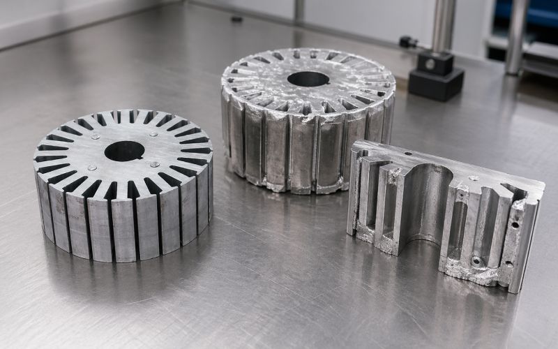
A rotor lamination stack is a tolerance stack in the literal sense.
Each lamination may be acceptable. The assembled stack may still create a difficult casting cavity.
Before releasing a rotor lamination design, review the worst acceptable case:
If the rotor only casts well at nominal dimensions, it is not production-ready.
Injection speed, aluminum temperature, die temperature, pressure, vacuum, venting, and lubrication all affect rotor casting quality.
But process settings cannot fully rescue poor geometry.
A narrow slot still restricts flow. A blind pocket still traps gas. A heavy end-ring junction still creates shrinkage risk. Excessive skew still lengthens the filling path.
Process tuning can reduce defects. It cannot remove the design cause every time.
This matters because production teams often get blamed for defects that were designed into the lamination stack.
A better approach is to review geometry and process together:
If the answer is weak, the drawing needs work.
Use this checklist before tooling release or when troubleshooting aluminum rotor casting defects.
| Review question | Why it matters |
|---|---|
| Is the slot opening large enough for stable aluminum entry? | Prevents short shots and unstable flow |
| Are there narrow necks leading into larger internal pockets? | Reduces gas entrapment risk |
| Is the slot bridge too thick for local solidification behavior? | Prevents early freezing near the slot top |
| Is the slot depth reasonable for the selected casting process? | Reduces long-path fill defects |
| Does skew create an excessive filling path? | Protects fill consistency and bar area |
| Are bar-to-end-ring transitions smooth? | Reduces shrinkage and weak junctions |
| Is end-ring mass controlled? | Avoids hot spots and porosity |
| Is burr direction specified? | Protects slot area and stack seating |
| Is stack compression defined? | Prevents flash between laminations |
| Are slot registration tolerances realistic? | Keeps the internal flow channel consistent |
| Has the design been checked at worst-case tolerance? | Avoids designs that only work at nominal condition |
| Are sectioning and resistance checks included in validation? | Confirms internal cage quality |
External inspection is useful, but it does not prove the rotor cage is sound.
Geometry-related defects often hide inside the lamination stack or near the end-ring junction.
Useful validation methods include:
Cutting sample rotors exposes bar fill, porosity, shrinkage, cold shuts, and bar-to-ring quality. It is destructive, but it gives direct evidence.
Resistance variation can reveal uneven bar quality or weak cage connections. It does not show the defect shape, but it can show that something is inconsistent.
Rotor weight trends can help detect fill variation. Weight alone is not enough, but sudden changes are worth investigating.
Porosity and uneven fill can affect mass distribution. Balance data can sometimes point toward casting asymmetry.
Locked-rotor current, torque behavior, heating, vibration, and efficiency can all reflect cage quality.
For critical rotors, internal inspection can identify porosity, shrinkage, or incomplete fill without cutting every sample.
No single test tells the whole story. The best validation uses several signals together.
Electrical performance matters. But if the slot cannot be filled consistently, the intended performance does not exist in production.
Skew can reduce certain motor problems. It can also create casting problems and reduce torque if overused.
The end ring is part of the electrical cage and part of the casting feed system. It should be reviewed early.
Porosity often has process causes. It can also have geometry causes. Most real cases involve both.
The CAD model is clean. The stack is not. Burrs, coatings, compression, and alignment change the cavity.
A slot can meet dimensional tolerance and still be difficult to fill. Castability needs its own review.
A better aluminum rotor design workflow looks like this:
Step 9 is where many teams stop too early.
A casting trial should not only approve or reject the process. It should teach the design what the aluminum is actually doing.
Rotor lamination geometry refers to the shape and arrangement of the punched steel laminations used to build the rotor core. It includes slot shape, slot opening, bridge thickness, skew, stack length, burr condition, and alignment.
The lamination stack forms the internal cavity that molten aluminum fills. Its geometry controls flow resistance, venting, cooling rate, solidification pattern, and final rotor bar quality.
Rotor slots can be long, narrow, skewed, or restricted near the opening. These features can slow aluminum flow, trap gas, or cause early freezing before the slot is fully filled.
Porosity risk increases with blind pockets, poor venting, narrow necks, heavy end-ring sections, abrupt bar-to-ring transitions, and areas where aluminum solidifies without proper feeding.
Yes. Skew increases the effective flow path and makes slot alignment more sensitive. It can improve motor behavior but may also increase filling difficulty if the angle is too aggressive.
Closed or semi-closed slots can offer some manufacturing and electromagnetic benefits, but they can also hide internal defects and create restrictions. The best choice depends on the full rotor design and casting process.
The bar-to-end-ring transition is where thin rotor bars meet a larger aluminum ring. This area is prone to shrinkage, weak feeding, and poor electrical connection if the section change is too abrupt.
They can help, but they cannot fully remove geometry-driven risk. If the slot traps air or the end ring creates a hot spot, process tuning may reduce defects but not eliminate the root cause.
Common methods include sectioning, resistance comparison, weight tracking, balance data, performance testing, and internal inspection for critical applications.
Design the lamination stack as part of the casting cavity. Review slot shape, skew, burrs, stack compression, venting, and end-ring transitions before tooling release. The best rotor geometry is not only efficient. It is repeatable in production.