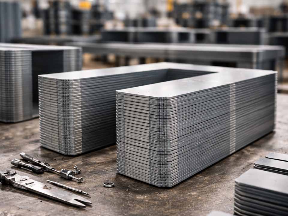
Let Sino's Lamination Stacks Empower Your Project!
To speed up your project, you can label Lamination Stacks with details such as tolerance, material, surface finish, whether or not oxidized insulation is required, quantity, and more.
Poor lamination stamping yield rarely starts with one dramatic failure. More often, it starts with small process shifts: burr growth, punch wear, strip misfeed, coating damage, slug pulling, stack misalignment, or coil-to-coil variation.
Each issue looks manageable on a single sheet.
Then the sheets become a stack.
A 20 μm burr repeated across hundreds of laminations is no longer “small.” A slight coating scratch becomes an interlaminar short risk. A feed error that passed visual inspection becomes slot mismatch, skew error, heat, noise, or failed assembly.
That is why lamination stamping needs a different troubleshooting mindset from ordinary sheet metal stamping. You are not only making a shape. You are protecting geometry, stack height, insulation, magnetic performance, and assembly repeatability at the same time.
| Production symptom | Check first | Likely root cause | Fast corrective action |
|---|---|---|---|
| Burr height keeps rising | Burr direction, punch edge, die button wear | Worn tooling, wrong clearance, poor alignment | Map burr by station, sharpen or replace local tooling, recheck clearance |
| Burr is high only on one side | Die alignment, press parallelism, guide wear | Uneven clearance, press deflection, loose components | Check shut height, guide system, stripper pressure, and station alignment |
| Stack height is too high | Lamination count, burr height, trapped chips | Burr buildup, wrong count, contamination | Verify count, clean stack path, reduce burr before stacking |
| Core runs hot after assembly | Interlaminar resistance, weld/stake area, edge burrs | Coating damage, burr bridges, excessive joining pressure or heat | Test before and after joining, reduce electrical contact paths |
| Slot or bore mismatch | Feed length, pilot condition, strip camber | Misfeed, worn pilots, poor strip control | Tune feeder, inspect pilots, control strip straightness |
| Random dents or scratches | Die surface, slug pulling, part transfer path | Pulled slugs, chips, rough handling | Improve slug retention, clean die contact zones, reduce sliding |
| Stack fans after release | Free-state flatness, burr direction, fixture release | Waviness, burr interference, uneven compression | Seat stack in stages, improve guides, inspect after unclamping |
| Punches break repeatedly | Punch load, clearance, lateral support | Too little clearance, tool deflection, poor stripping | Increase support, review clearance, improve stripping force balance |
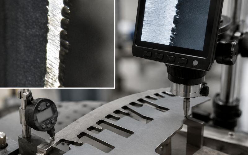
Clearance controls edge quality, burr height, punch load, slug behavior, and tool life. It also affects magnetic performance because a damaged cut edge can increase local stress and create paths for interlaminar contact.
For thin electrical steel, a trial clearance window often starts around 3% to 8% of sheet thickness per side. General stamping work may start closer to 5% to 10% per side, but lamination work should not copy a broad rule without testing. A 0.35 mm sheet at 5% per side means about 0.0175 mm clearance per side. That sounds tiny because it is.
Too little clearance can overload the punch and create secondary burrs. Too much clearance can increase rollover, fracture angle, and edge tearing. Uneven clearance is usually worse than either one.
Fix it
Measure burr height at fixed points, not random points. Compare entry side and exit side. If burr growth is uniform around the part, inspect tool wear first. If burr growth is stronger on one side, check die alignment, guide wear, stripper balance, and press parallelism before changing clearance.
Verify it
After adjustment, run a short trial and inspect burr height, edge fracture, slug shape, and punch load. Do not approve the setting from one first-off sample.
A sharp punch cuts. A worn punch drags, folds, heats, and tears.
Tool wear often hides behind “still running.” The die keeps cycling. Parts keep coming out. Then assembly yield drops because laminations no longer sit flat, burrs scrape coating, or slots begin drifting out of tolerance.
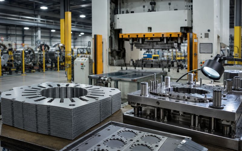
In lamination stamping, local wear matters. One worn slot punch can damage every layer in the stack.
Fix it
Track wear by station. Do not only count total press strokes. Stroke count is useful, but it misses material changes, lubrication changes, and coating abrasiveness.
Set sharpening triggers using a mix of:
Verify it
Compare parts before and after sharpening under the same coil, same speed, and same lubrication condition. Otherwise, the improvement may be blamed on the wrong variable.
A progressive lamination die depends on repeatable feed length and stable strip position. If the strip moves slightly, the die may still run, but the lamination geometry begins to lose registration.
This is dangerous because some misfeed defects are not obvious on a loose lamination. They appear later as skew error, tooth mismatch, bore runout, poor stacking, or assembly interference.
Fix it
Check feed length under production speed, not only during slow setup. Inspect pilot holes for signs of forcing, dragging, or oval wear. A pilot should locate the strip, not rescue a bad feed every stroke.
Also check strip camber. If the coil enters the die with side bow, the tool is forced to correct material movement continuously.
Verify it
Measure slot-to-bore position, tooth pitch, and pilot hole condition over several hundred strokes. A stable first piece does not prove stable progression.
Yield can drop even when the die has not changed.
That usually means the material changed.
Electrical steel variation can show up in thickness, hardness, coating condition, flatness, residual stress, camber, surface cleanliness, and burr response. Two coils with the same nominal grade can behave differently in the die.
This is not a theory problem. It is a lot-traceability problem.
Fix it
Tie every yield report to coil ID. At incoming inspection, check more than paperwork. Measure thickness, camber, flatness, coating condition, and surface contamination. For critical programs, run a short burr-response check before full production.
Verify it
When yield drops after a coil change, compare the defect start time with the coil transition. If the problem begins within the first few hundred strokes after changeover, do not start by blaming the die.
The coating on electrical steel is thin, but it has a large job. It helps keep eddy currents inside individual laminations instead of allowing current paths between sheets.
Coating damage can happen during stamping, part transfer, stacking, interlocking, welding, bonding, or compression. The part may look fine. The stack may still fail electrical isolation.
Common damage points include slot edges, bore edges, weld zones, guide-pin contact areas, and places where laminations slide under pressure.
Fix it
Inspect coating before and after stamping. These are separate checks. Incoming coating may be acceptable, then damaged by rough tooling, trapped chips, poor lubrication, or aggressive handling.
Reduce sliding contact between laminations. Sliding under load is one of the easiest ways to turn good coating into a weak insulation path.
Verify it
Run interlaminar resistance or isolation checks before and after joining. If the stack only fails after staking, welding, or compression, the stamping process may not be the only cause.
Slug pulling can ruin yield quickly. A pulled slug can dent the next lamination, scratch coating, break a punch, block a feature, or create double-hit damage.
Fine chips are quieter but still costly. They sit on the strip, enter the stack, or get pressed into the coating. One particle can affect stack height. Several particles can create false seating or local electrical contact.
Fix it
Look at slug behavior directly. Do not guess. Check whether slugs stick to punches, bounce out of die buttons, or ride back up with oil film.
Possible corrections include:
Verify it
Inspect the next ten to twenty parts after a slug event. Damage often appears after the first visible incident.
Flat laminations stack well. Wavy laminations fight the fixture.
Waviness can come from coil set, poor leveling, uneven cutting forces, stress release after stamping, bad ejection, or rough part handling. The stack may look acceptable while clamped, then fan or lean after release.
That is a common trap. A fixture can hide a bad stack.
Fix it
Measure flatness in two ways: free-state and under controlled load. Both matter. If the lamination is only flat under force, expect trouble during assembly or after thermal cycling.
Review how parts leave the die. Thin laminations can distort during ejection, drop, collection, or transfer.
Verify it
Inspect stack alignment after unclamping. If the stack shifts after release, adjust seating sequence, guide fit, burr direction, and compression balance.
Stack alignment is part of yield, not a secondary operation.
Interlocking, staking, bonding, and welding all help hold laminations together. They can also create distortion, local stress, coating damage, or electrical contact between sheets.
Misalignment usually comes from a combination of burrs, poor guide fit, uneven compression, worn stacking pins, inconsistent lamination orientation, or joining force that moves the stack before it is fully seated.
Fix it
Locate gently first. Then seat. Then compress. Then join.
Do not force guide pins to act like correction tools. If pins scrape the inner diameter or slot edges, they may solve alignment while damaging coating.
For welded stacks, reduce unnecessary heat input and weld length. For bonded stacks, check adhesive thickness and squeeze-out. For staked stacks, check whether the stake is locking the stack or distorting it.
Verify it
Measure runout, stack height, and interlaminar resistance before and after joining. If the defect appears only after joining, the joining process needs its own control plan.
A good die can still make bad laminations in an unstable press.
Press issues include poor slide parallelism, inconsistent bottom-dead-center position, off-center loading, vibration, worn gibs, weak foundation, or unstable shut height. These problems create changing clearance during the stroke.
The defect may look like random burr variation. It is often not random.
Fix it
Check press condition under load. Static checks are useful, but lamination dies run at speed, with real force and real vibration.
Review tonnage signature if available. Sudden load changes can point to slug pulling, dull punches, material thickness variation, or feed problems.
Verify it
Compare burr height and feature size from left, right, front, and rear areas of the strip. If one area consistently behaves differently, inspect press alignment and die loading balance.

Late inspection creates expensive scrap.
If the first real check happens after stacking, bonding, welding, or final assembly, the process is already losing money. Lamination stamping needs upstream signals.
A good inspection plan should catch:
Fix it
Move inspection closer to the cause. For example, if stack height is unstable, do not only measure finished stacks. Measure lamination thickness, burr height, part count, and trapped contamination before joining.
Verify it
Every major defect should have an earlier warning signal. If no upstream signal exists, create one.
These are starting points, not universal specifications. Final limits should be validated against the material grade, sheet thickness, stack design, joining method, and electrical performance requirements.
| Control item | Useful starting target | Why it matters |
|---|---|---|
| Punch-to-die clearance | About 3–8% of sheet thickness per side for many thin electrical steel trials | Controls burr, edge quality, punch load, and slug behavior |
| General burr warning level | Investigate before burr height approaches 10% of sheet thickness | High burrs can affect stacking, insulation, and assembly |
| Precision lamination burr target | Often controlled in the tens of microns; tighter for high-efficiency cores | Small burrs repeat across the full stack |
| Feed repeatability | Tight enough to protect slot-to-bore and tooth pitch tolerance | Prevents skew, mismatch, and stacking error |
| Stack inspection point | Before and after joining | Separates stamping defects from joining defects |
| Coating inspection | Incoming, after stamping, after stacking/joining | Finds where insulation damage actually begins |
Use a three-step loop.
First, define the symptom in measurable terms. Not “bad burrs.” Write “exit-side burr at slot station 6 increased from 12 μm to 32 μm over 80,000 strokes.”
Second, connect the symptom to the earliest process signal. Burr height may point to tool wear. One-sided burr may point to alignment. Stack height may point to burr buildup, wrong count, thickness variation, or chips.
Third, verify the fix after a short production run. Many fixes look good on the first part and fail after the die warms up, the oil film changes, or the strip reaches full speed.
The process is not complicated. It just has to be disciplined.
The most common cause is uncontrolled burr growth, often linked to tool wear, incorrect clearance, die misalignment, or material variation. Burrs create problems beyond the stamped edge. They can affect stack height, coating integrity, interlaminar insulation, and final assembly.
For many thin electrical steel applications, clearance trials often begin around 3% to 8% of sheet thickness per side. General sheet metal rules may start around 5% to 10% per side. The right value must be proven by burr height, edge quality, punch load, slug behavior, and magnetic performance.
There is no single universal limit. A common general warning level is 10% of sheet thickness, but precision motor or transformer laminations often need much tighter control, commonly in the tens of microns. The correct limit should be based on stack height, electrical isolation, and final performance.
Stack height can increase because of excessive burrs, trapped chips, wrong lamination count, sheet thickness variation, waviness, or poor seating during compression. Check count and thickness first, then burr height and contamination.
Interlaminar shorts can come from burr bridges, coating scratches, excessive stacking pressure, staking deformation, weld heat, or debris trapped between sheets. Test before and after joining to find where the short is introduced.
Start by checking clearance, oil film, punch condition, die button relief, stripper pressure, and slug retention. Sticky lubricant, trapped air, magnetic tools, and fast piercing can all contribute. Fix the local station instead of treating the whole die as the problem.
Coils can vary in thickness, hardness, coating behavior, flatness, camber, residual stress, and surface condition. Keep coil ID connected to burr data, feed stability, stack height, and electrical test results.
Measure at first-off, after coil changes, after tool maintenance, after process changes, and at intervals based on tool wear history. For high-volume production, trend-based inspection is better than a fixed interval alone.