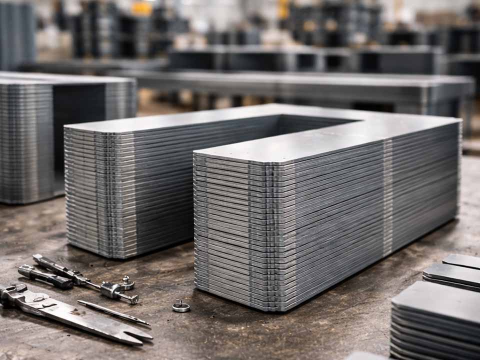
Let Sino's Lamination Stacks Empower Your Project!
To speed up your project, you can label Lamination Stacks with details such as tolerance, material, surface finish, whether or not oxidized insulation is required, quantity, and more.
A lamination short is an unintended electrical path between adjacent electrical steel laminations. It allows eddy currents to spread across sheets instead of staying confined within each sheet, which can increase core loss, create local hot spots, and reduce the efficiency of motor stators, transformer cores, and other silicon steel lamination stacks.
That is the clean definition.
The messy part is this: a short is not always obvious. It may start as a burr at a slot edge. Or a crushed coating under stack pressure. Or a small conductive particle trapped between two sheets. The stack may pass one inspection, then fail after welding, bonding, machining, or final compression.
So detection has to follow the process, not just the finished part.
A laminated core is built from thin electrical steel sheets. Each sheet has an insulating coating to limit current flow between layers. The core should act as a magnetic path, not as one solid conductive block.
A lamination short happens when that insulation is bypassed.
It may connect only two sheets. It may bridge a larger section through a burr, weld, rivet, clamp, interlock, machining smear, or corroded edge. The serious cases are the ones that create a circulating current path. That path generates heat. Sometimes in one tooth. Sometimes near the back iron. Sometimes at a slot corner where winding insulation is already under stress.
Not every low-resistance spot destroys a core. Some are small and isolated. But a repeatable hot spot is different. Treat it as a fault until proven otherwise.
Most lamination shorts are process-made. They are rarely mysterious once you trace the part history.
| Cause | What physically happens | Common location | What to check first |
|---|---|---|---|
| Punching or stamping burrs | Raised metal cuts through coating and touches the next sheet | Slot edges, tooth tips, inner diameter, outer diameter | Burr height, burr direction, die clearance |
| Excessive stack pressure | Coating is crushed or displaced under load | Clamped zones, press-fit areas, interlocks | Press force, flatness, stack height variation |
| Welding or thermal joining | Heat burns coating or creates a conductive bridge | Weld seams, tabs, outer diameter | Weld depth, heat input, repeat fault angle |
| Machining after stacking | Metal smear crosses lamination lines | Bore, OD, keyway, slot openings | Tool wear, grinding marks, metal dust |
| Conductive contamination | Chips, dust, coolant residue, or carbon creates leakage | Faces, edges, slot bottoms | Cleaning, drying, handling controls |
| Corrosion | Rust and edge damage disturb insulation and contact pressure | Cut edges, stored stacks | Storage humidity, packaging, edge condition |
| Coating defects | Surface insulation is weak before stacking | Full sheet surface or lot-specific areas | Coating test data, supplier lot history |
| Handling damage | Scratches or dents expose base steel | Corners, locating holes, random faces | Transport trays, fixtures, operator handling |
A short found at final test may have started much earlier. That is why a good root-cause review asks: did the short appear after cutting, after stacking, after joining, or after machining?
A shorted lamination stack often leaves clues before it becomes a failed core.
Look for:
One clue is not enough. Two or three together are worth stopping for.
Visual inspection is basic, but it still catches real problems.
Use angled light and magnification. Straight-on inspection hides burrs. Side lighting shows raised metal, scratches, smear, rust, and coating damage more clearly.
Pay close attention to:
Do not over-trust a clean-looking stack. Many shorts are pressure-dependent. The part can look fine loose and fail after compression.
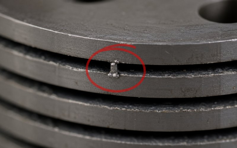
Burrs are one of the most common causes of motor stator lamination shorts and transformer core edge shorts.
Burr height matters. Direction matters too.
A burr pointing into the next sheet can pierce coating during stacking. If every lamination is oriented the same way, burrs can form a repeated conductive path through the stack. This is why burr inspection should be tied to die maintenance, sharpening cycle, material thickness, and stacking orientation.
A useful production habit: record burr data by tool station, not just by batch. Faults often follow tooling.
There are two related checks, and they should not be confused.
Surface insulation resistivity testing, often associated with the Franklin test method, evaluates the surface coating of single strips or punchings under defined voltage and pressure conditions. It is useful for incoming material checks and coating quality control.
Interlaminar resistance testing checks resistance between adjacent coated surfaces. This is closer to the actual question: can current pass from one lamination to the next?
For production control, test under repeatable conditions:
A random number has limited value. A trend has value. If readings drop after stacking pressure, the insulation system may be failing only in the assembled state.
A megohmmeter is useful, but not as a primary lamination-to-lamination short detector.
It is better suited for gross insulation checks such as core-to-frame, winding-to-ground, or insulated hardware checks. It can catch large leakage paths. It cannot prove that interlaminar insulation is healthy throughout a stack.
This point matters. A stack can pass a megohmmeter check and still have local shorted laminations that create heat under magnetic excitation.
Use it. Just do not let it make the final decision.
Core loss testing measures how much power the core consumes under controlled magnetic conditions. If a lamination stack has shorted paths, core loss can rise because eddy currents have more room to circulate.
This test is useful for:
Core loss testing tells you the stack is wasting energy. It may not tell you exactly where the short is. For that, pair it with thermal inspection or localized magnetic scanning.
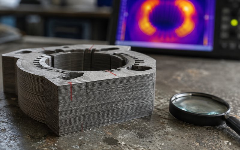
Thermal imaging is practical because lamination shorts often reveal themselves as local hot spots.
The core is excited under controlled conditions, then scanned for abnormal temperature rise. The fault area usually heats faster than surrounding steel and appears in the same place when the test is repeated.
Be careful with false readings. Oil, paint, airflow, shiny metal, tape, and camera angle can distort thermal results. A real fault should repeat. It should grow with excitation. It should not disappear because the camera moved.
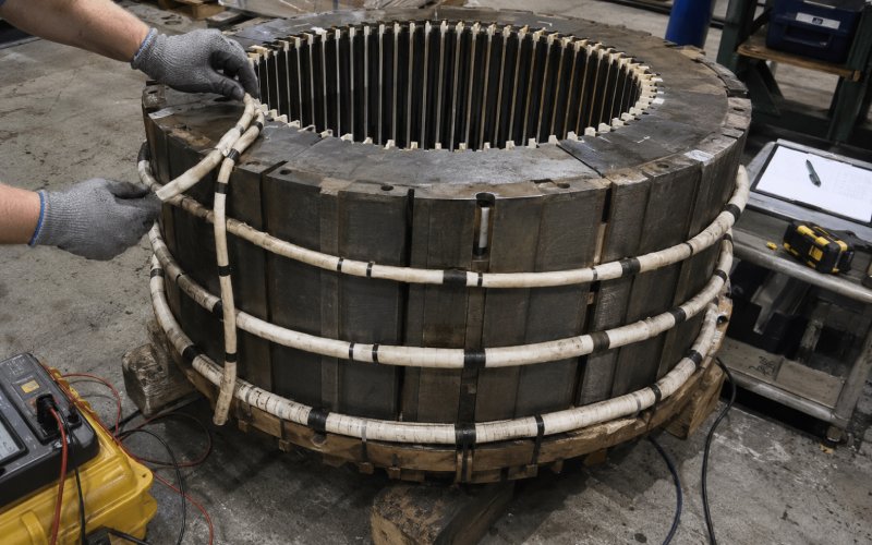
For large motor and generator stator cores, electromagnetic core imperfection detection, often shortened to ELCID, is used to find interlaminar insulation faults at low flux levels.
The advantage is simple: it can detect suspicious areas without driving the core into a full heating test. It is useful when a full-flux test is difficult, expensive, or risky.
Still, interpretation takes care. Slot geometry, test setup, core condition, and operator technique affect readings. ELCID is strong as a location tool. It should be paired with inspection judgment, not treated as an automatic pass/fail button.
A core loop test, also called a loop test or full-flux core test, magnetizes the core closer to service conditions and checks for abnormal heating or loss.
This is often used for large stator cores, rewound machines, repair verification, or high-consequence equipment. It needs more power, setup time, and safety control than low-flux methods.
Use it when the question is not just “is there a flaw?” but “will this core heat under real magnetic loading?”
| Method | Best use | What it finds well | Main limitation |
|---|---|---|---|
| Visual inspection | Fast screening | Burrs, smear, rust, handling damage | Misses hidden and pressure-dependent shorts |
| Burr measurement | Stamped laminations | Tool wear and edge risk | Does not confirm electrical contact |
| Franklin-type surface test | Single sheets or punchings | Coating surface quality | Not a finished-stack test |
| Interlaminar resistance test | Adjacent coated surfaces | Layer-to-layer insulation weakness | Sensitive to pressure and contact setup |
| Megohmmeter check | Gross insulation paths | Core-to-frame or ground faults | Weak for local lamination shorts |
| Core loss test | Finished stacks | Excess magnetic loss | May not locate the fault |
| Thermal imaging | Energized cores | Local hot spots | Needs controlled excitation |
| ELCID test | Large stator cores | Low-flux fault location | Needs trained interpretation |
| Core loop test | Large or critical cores | Heating under high-flux conditions | Setup-heavy |
False alarms happen. Bad probe contact looks like a fault. Dust comes and goes. Moisture changes readings. Fixtures can trick you.
A real lamination short usually has a pattern:
That last one is easy to forget. Mark the stack orientation before testing. If the fault follows the part, it is in the part. If it stays with the test stand, fix the test stand.
Detection is useful. Prevention is cheaper.
Control these process points:
A good stack is usually the result of ordinary discipline. Sharp tools. Clean parts. Known pressure. Verified insulation. No guesswork hiding in the middle.
For purchasing teams, the real question is not “can this supplier stamp steel?” Many can.
The better question is: can they prove the stack will keep interlaminar insulation after cutting, stacking, joining, and final inspection?
Ask these RFQ questions:
| Audit question | Why it matters |
|---|---|
| What burr height limit is used for this lamination geometry? | Generic burr limits may not protect narrow teeth or slot edges. |
| How is burr direction controlled during stacking? | Aligned burrs can create repeated short paths. |
| What coating type and insulation test data are available? | Coating performance should be verified before assembly. |
| Are surface insulation or interlaminar resistance tests performed? | This shows whether insulation is measured, not assumed. |
| Is core loss testing available for finished stacks? | Finished behavior matters more than loose-sheet approval. |
| How are welding, bonding, or interlocking effects validated? | Joining can create shorts after earlier tests pass. |
| Is final machining controlled to prevent metal smear? | Machining can bridge layers at the bore or OD. |
| Are inspection reports traceable by lot and process step? | Traceability makes root cause possible when failures appear. |
A supplier who can answer these clearly is easier to trust. A supplier who only says “we have QC” is asking you to take the risk.
Sometimes.
Minor edge shorts may be removed by controlled deburring, careful cleaning, local insulation repair, or separating and re-insulating affected areas. In large stator cores, local repair may involve removing conductive bridges, cleaning damaged regions, inserting suitable insulation, and retesting.
Severe faults are different. Burned coating, deep weld damage, heavy corrosion, or machining smear across many layers may require restacking or replacement.
The repair is not finished when the mark disappears. It is finished when resistance, core loss, thermal behavior, or magnetic fault testing confirms the fault is gone.
A lamination short is an unintended electrical connection between adjacent steel laminations in a magnetic core. It bypasses the insulation coating and can increase eddy-current loss.
Common causes include punching burrs, excessive stack pressure, welding heat, machining smear, conductive dust, corrosion, and coating damage during handling.
No. A lamination short occurs in the steel core. A winding short occurs in the copper or aluminum winding. A lamination short can create heat that later damages winding insulation, but they are different faults.
Yes. A megohmmeter can find gross insulation faults, but it is not enough to prove interlaminar insulation health. Core loss testing, thermal imaging, ELCID testing, or interlaminar resistance testing may still be needed.
For loose sheets, use coating and interlaminar resistance checks. For finished stacks, use core loss and thermal testing. For large stator cores, ELCID and core loop testing are common options.
ELCID is a low-flux method used to locate core imperfections. A core loop test uses higher magnetic excitation to check heating and loss closer to operating conditions.
Yes. A burr can pierce the insulation coating and connect adjacent laminations. If it becomes part of a circulating current path, it can create localized heating.
Control burrs, coating damage, stacking pressure, joining heat, contamination, corrosion, and post-stack machining. Test at more than one process stage, not only at final inspection.
A lamination short is not just a small electrical defect. It is a process signal.
It tells you something about cutting, coating, stacking, pressure, joining, machining, cleaning, or storage. Sometimes more than one.
The strongest inspection plan checks the lamination before stacking, the stack after compression, and the finished core under magnetic excitation. That is how motor stator and transformer core manufacturers reduce hot spots, lower core loss, and avoid failures that show up too late.
Need precision lamination stacks with controlled burrs, verified insulation performance, and core-loss inspection? Send the drawing, material grade, stack height, joining method, and test requirements for an engineering review.